7411(2017) 데이터 시트보기 (PDF) - Analog Devices
부품명
상세내역
일치하는 목록
7411
(Rev.:2017)
(Rev.:2017)
Analog Devices

7411 Datasheet PDF : 36 Pages
| |||
ADT7411
The measured results from the temperature sensors are
compared with the internal and external THIGH and TLOW
limits. These temperature limits are stored in on-chip registers.
If the temperature limits are not masked out, any out-of-limit
comparisons generate flags that are stored in Interrupt Status 1
register. One or more out-of-limit results causes the INT/INT
output to pull either high or low, depending on the output
polarity setting.
Theoretically, the temperature measuring circuit can measure
temperatures from –128°C to +127°C with a resolution of
0.25°C. However, temperatures outside TA are outside the
guaranteed operating temperature range of the device.
Temperature measurement from –128°C to +127°C is
possible using an external sensor.
Temperature measurement is initiated by three methods. The
first method is applicable when the part is in single-channel
measurement mode. The temperature is measured 16 times and
internally averaged to reduce noise. In single-channel mode, the
part is continuously monitoring the selected channel, that is, as
soon as one measurement is taken, another one is started on the
same channel. The total time to measure a temperature channel
with the ADC operating at slow speed is typically 11.4 ms
(712 μs × 16) for the internal temperature sensor and 24.22 ms
(1.51 ms × 16) for the external temperature sensor.
S/W RESET
Data Sheet
The new temperature value is stored in two 8-bit registers and
ready for reading by the I2C or SPI interface. The user has the
option of disabling the averaging by setting Bit 5 in the Control
Configuration 2 register (Address 19h). The ADT7411
defaults on power-up with the averaging enabled.
The second method is applicable when the part is in round
robin measurement mode. The part measures both the internal
and external temperature sensors as it cycles through all possible
measurement channels. The two temperature channels are
measured each time the part runs a round robin sequence.
In round robin mode, the part is continuously measuring all
channels.
Temperature measurement is also initiated after every read
or write to the part when the part is in either single-channel
measurement mode or round robin measurement mode. Once
serial communication has started, any conversion in progress
is stopped and the ADC is reset. Conversion starts again
immediately after the serial communication has finished.
The temperature measurement proceeds normally as
previously described.
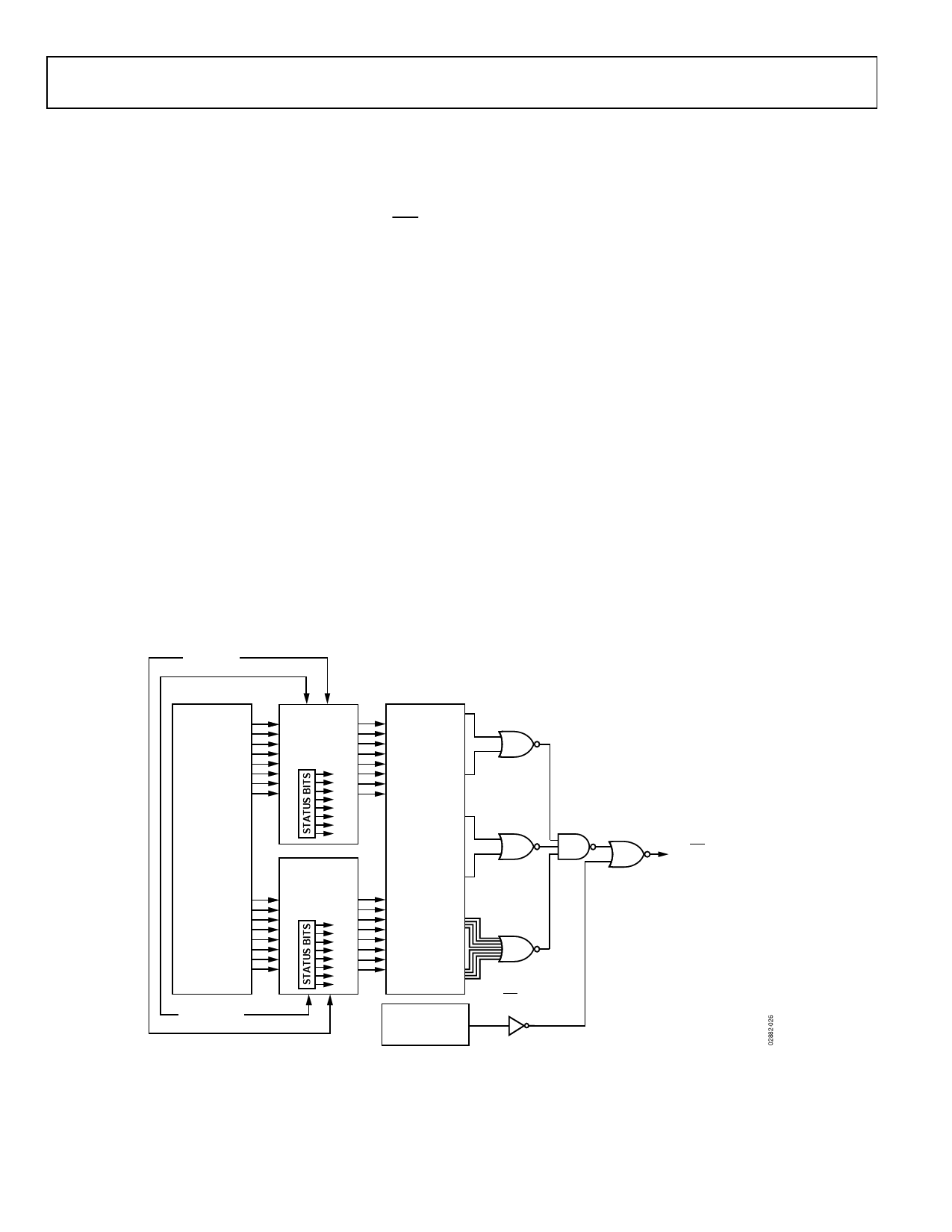
INTERRUPT
STATUS
REGISTER 1
(TEMP AND
AIN1 TO AIN4)
INTERNAL
TEMP
EXTERNAL
TEMP
WATCHDOG
LIMIT
COMPARISONS
INTERRUPT
STATUS
REGISTER 2
(VDD AND
AIN5 TO AIN8)
INTERRUPT
MASK
REGISTERS
VDD
DIODE
FAULT
AIN1 TO AIN4
READ RESET
AIN5 TO AIN8
CONTROL
CONFIGURATION
REGISTER 1
INT/INT
ENABLE BIT
Figure 27. ADT7411 Interrupt Structure
INT/INT
(LATCHED OUTPUT)
Rev. C | Page 16 of 36
Share Link: