PCA9542 데이터 시트보기 (PDF) - Philips Electronics
부품명
상세내역
일치하는 목록
PCA9542 Datasheet PDF : 10 Pages
| |||
Philips Semiconductors
2-channel I2C multiplexer and interrupt controller
Product specification
PCA9542
CHARACTERISTICS OF THE I2C-BUS
The I2C-bus is for 2-way, 2-line communication between different ICs
or modules. The two lines are a serial data line (SDA) and a serial
clock line (SCL). Both lines must be connected to a positive supply
via a pull-up resistor when connected to the output stages of a device.
Data transfer may be initiated only when the bus is not busy.
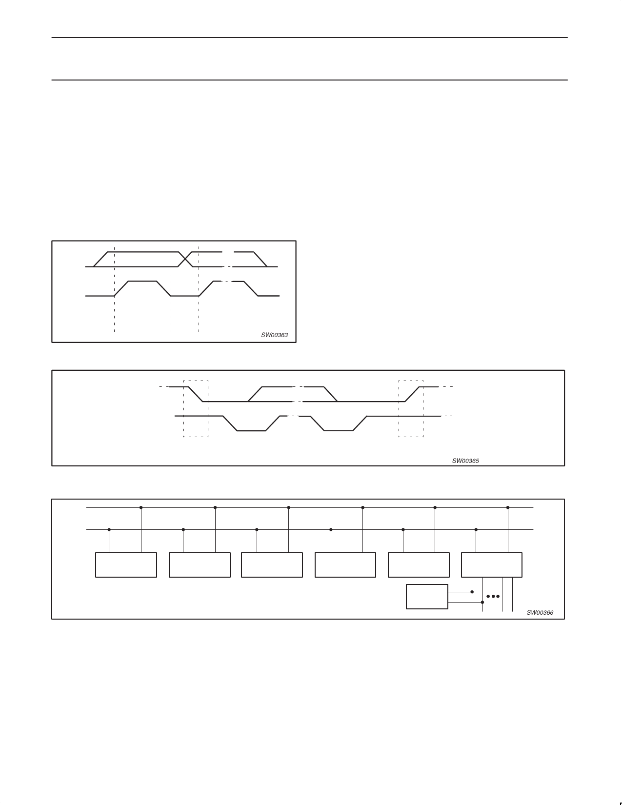
Bit transfer
One data bit is transferred during each clock pulse. The data on the
SDA line must remain stable during the HIGH period of the clock
pulse as changes in the data line at this time will be interpreted as
control signals (see FIgure 1).
Start and stop conditions
Both data and clock lines remain HIGH when the bus is not busy. A
HIGH-to-LOW transition of the data line, while the clock is HIGH is
defined as the start condition (S). A LOW-to-HIGH transition of the
data line while the clock is HIGH is defined as the stop condition (P)
(see Figure 2).
System configuration
A device generating a message is a transmitter: a device receiving
is the receiver. The device that controls the message is the master
and the devices which are controlled by the master are the slaves
(see Figure 3).
SDA
SCL
data line
stable;
data valid
change
of data
allowed
SW00363
Figure 1. Bit transfer
SDA
SDA
SCL
S
SCL
P
START condition
STOP condition
Figure 2. Definition of start and stop conditions
SW00365
SDA
SCL
MASTER
TRANSMITTER/
RECEIVER
SLAVE
RECEIVER
SLAVE
TRANSMITTER/
RECEIVER
MASTER
TRANSMITTER
Figure 3. System configuration
MASTER
TRANSMITTER/
RECEIVER
SLAVE
I2C
MULTIPLEXER
SW00366
1999 Oct 07
5
Share Link: 