IRFD1Z0 데이터 시트보기 (PDF) - Intersil
부품명
상세내역
일치하는 목록
IRFD1Z0 Datasheet PDF : 6 Pages
| |||
IRFD1Z0, IRFD1Z1, IRFD1Z2, IRFD1Z3
Electrical Specifications TC = 25oC, Unless Otherwise Specified (Continued)
PARAMETER
SYMBOL
TEST CONDITIONS
MIN TYP MAX UNITS
Internal Drain Inductance
Internal Source Inductance
LD
Measured From The
Modified MOSFET
- 4.0 -
nH
Drain Lead, 2mm
Symbol Showing the
(0.08in) From Package Internal Devices
to Center of Die
Inductances
LS
Measured From The
Source Lead, 2mm
D
- 6.0 -
nH
LD
(0.08in) From Header to
Source Bonding Pad
G
LS
Thermal Resistance Junction to Ambient
RθJA Free Air Operation
S
-
-
120 oC/W
Source to Drain Diode Specifications
PARAMETER
SYMBOL
TEST CONDITIONS
MIN TYP MAX UNITS
Continuous Source to Drain Current
IRFD1Z0, IRFD1Z1
IRFD1Z2, IRFD1Z3
Pulse Source to Drain Current
IRFD1Z0, IRFD1Z1
IRFD1Z2, IRFD1Z3
ISD
ISDM
Modified MOSFET
Symbol Showing the
Integral Reverse
P-N Junction Diode
G
D
-
-
0.5
A
-
-
0.4
A
-
-
4.0
A
S
-
-
3.2
A
Source to Drain Diode Voltage (Note 2)
IRFD1Z0, IRFD1Z1
IRFD1Z2, IRFD1Z3
Reverse Recovery Time
Reverse Recovery Charge
VSD
TA = 25oC, ISD = 0.5A, VGS = 0V
-
-
1.4
V
TA = 25oC, ISD = 0.4A, VGS = 0V
-
-
1.3
V
trr
TJ = 150oC, ISD = 0.5A, dISD/dt = 100A/µs
-
100
-
ns
QRR
TJ = 150oC, ISD = 0.5A, dISD/dt = 100A/µs
-
0.2
-
µC
NOTES:
2. Pulse test: pulse width ≤ 300µs, duty cycle ≤ 2%.
3. Repetitive rating: pulse width limited by maximum junction temperature.
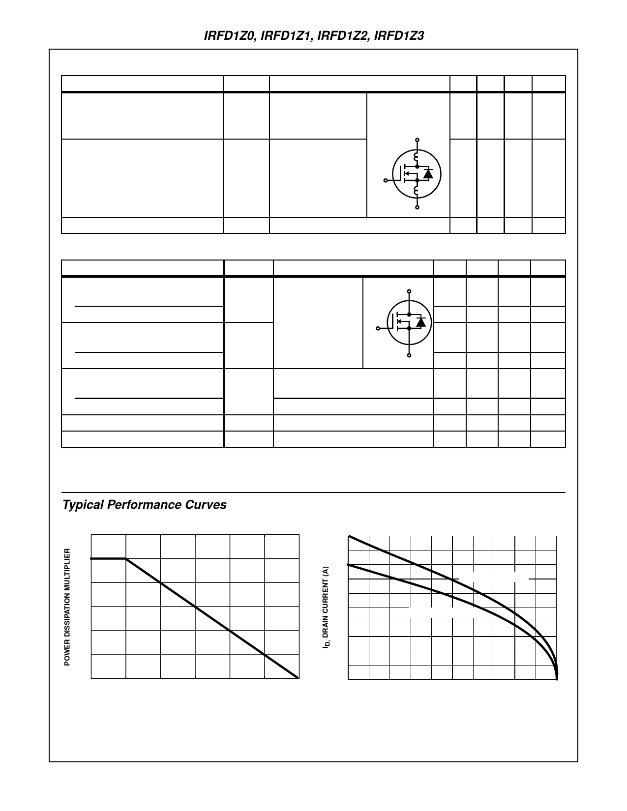
Typical Performance Curves Unless Otherwise Specified
1.2
0.5
1.0
0.4
IRFD1Z0, IRFD1Z1
0.8
0.3
0.6
IRFD1Z2, IRFD1Z3
0.2
0.4
0.2
0.1
0.0
0
25
50
75
100
125
150
TA, AMBIENT TEMPERATURE (oC)
0
25
50
75
100
125
150
TA, AMBIENT TEMPERATURE (oC)
FIGURE 1. NORMALIZED POWER DISSIPATION vs
AMBIENT TEMPERATURE
FIGURE 2. MAXIMUM CONTINUOUS DRAIN CURRENT vs
AMBIENT TEMPERATURE
5-3
Share Link: 