NC12S0A0H15 데이터 시트보기 (PDF) - Unspecified
부품명
상세내역
일치하는 목록
NC12S0A0H15 Datasheet PDF : 14 Pages
| |||
FEATURES DESCRIPTIONS (CON.)
Power Good
The converter provides an open collector signal called
Power Good. This output pin uses positive logic and is
open collector. This power good output is able to sink
5mA and set high when the output is within ±10% of
output set point.
The power good signal is pulled low when output is not
within ±10% of Vout or Enable is OFF.
Current Sink Capability
The NC series converters are able to sink current as well
as function as a current source. It is able to sink the full
output current at any output voltage up to and including
2.5V. This feature allows the NC series fit into any
voltage termination application.
Voltage Margining Adjustment
Output voltage margin adjusting can be implemented in
the NC modules by connecting a resistor, Rmargin-up, from
the Trim pin to the Ground for for margining up the output
voltage. Also, the output voltage can be adjusted lower
by connecting a resistor, R , margin-down from the Trim pin to
the voltage source Vt. Figure 30 shows the circuit
configuration for output voltage margining adjustment.
NC6A/15A/20A
Vout
Vin
Enable
Ground
Trim
Rs
Ground
Vt
Rmargin-down
Rmargin-up
Figure 30: Circuit configuration for output voltage margining
Paralleling
NC06/NC15/NC20 converters do not have built-in current
sharing (paralleling) ability. Hence, paralleling of multiple
NC06/NC15/NC20 converters is not recommended.
Output Capacitance
There is no output capacitor on the NC series modules.
Hence, an external output capacitor is required for stable
operation. For NC15 modules, an external 6.3V/680μF
low ESR capacitor (for example, OSCON) is required for
stable operation.
It is important to places these low ESR capacitors as
close to the load as possible in order to get improved
dynamic response and better voltage regulation,
especially when the load current is large. Several of these
low ESR capacitors could be used together to further
lower the ESR.
Please refer to individual datasheet for the maximum
allowed start-up load capacitance for each NC series as it
is varied between series.
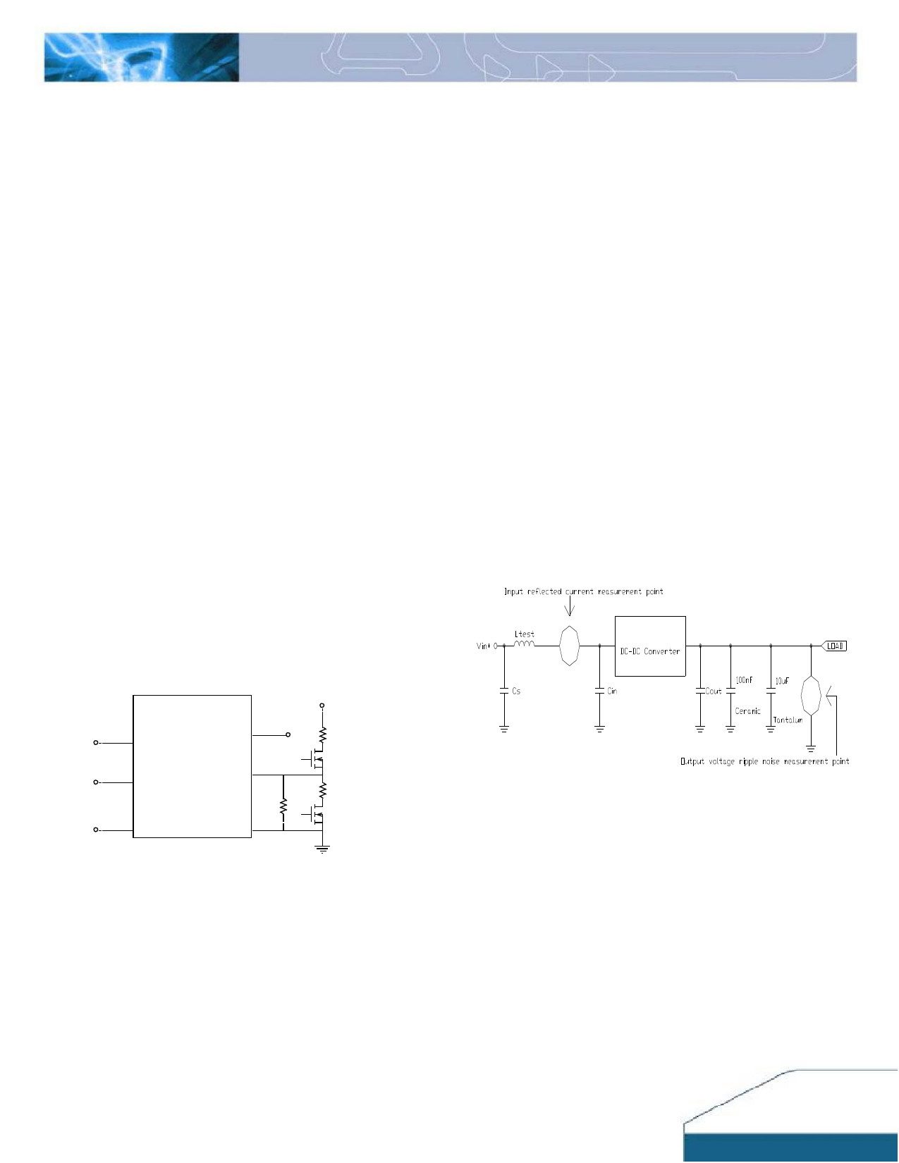
Reflected Ripple Current and Output Ripple and
Noise Measurement
The measurement set-up outlined in Figure 31 has been
used for both input reflected/ terminal ripple current and
output voltage ripple and noise measurements on NC
series converters.
Cs=270μF*1, Ltest=1.4μH, Cin=270μF*1, Cout=680μF *1
Figure 31: Input reflected ripple/ capacitor ripple current and
output voltage ripple and noise measurement setup for NC15
NC12S15A_12022010
9
Share Link: 