AD1984 데이터 시트보기 (PDF) - Analog Devices
부품명
상세내역
일치하는 목록
AD1984 Datasheet PDF : 20 Pages
| |||
AD1984
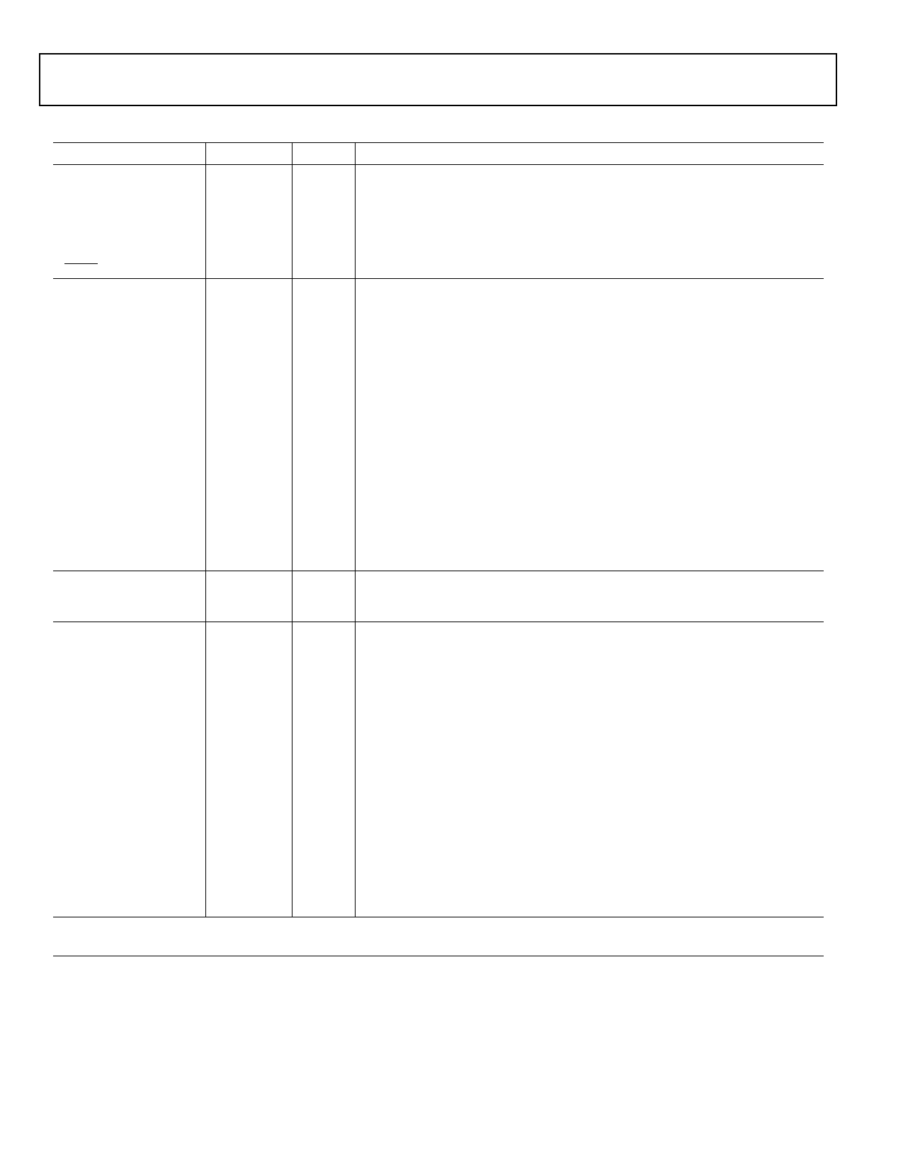
Table 3. AD1984 Pin Descriptions
Mnemonic
Pin No.
I/O
Description
DIGITAL INTERFACE
SDATA_OUT
5
BIT_CLK
6
SDATA_IN
8
SYNC
10
RESET
11
DIGITAL I/O
DM_1/DM_2
2
DM_3/DM_4
4
DM_CLK
46
GPIO_2
30
GPIO_1/MIC_BIAS-E 31
GPIO_0/EAPD
47
S/PDIF_OUT
48
JACK SENSE AND EAPD
SENSE_A/SRC_B
13
SENSE_B/SRC_A
34
ANALOG I/O
PCBEEP
12
Port E_L
14
Port E_R
15
Port F_L
16
Port F_R
17
CD_GND
19
I
Link Serial Data Output. AD1984 input stream. Clocked on both edges of the
BIT_CLK.
I
Link Bit Clock. 24.000 MHz serial data clock .
I/O
Link Serial Data Input. AD1984 output stream clocked only on one edge of BIT_CLK.
I
Link Frame Sync.
I
Link Reset. AD1984 master hardware reset.
I
Digital microphone 1 and 2 inputs (for bi-phase microphones), or digital microphone
1 input (for single-phase microphones).
I
Digital microphone 3 and 4 inputs (for bi-phase microphones), or digital microphone
2 input (for single-phase microphones).
O
Clock to drive external digital microphones.
I/O
General Purpose Input/Output Pins. Digital signals used to control or sense external
circuitry.
I/O
General Purpose I/O/Microphone Bias for Port E. Capable of Hi-Z, 1.65 V, and 2.86 V.
Pin 31 shares functionality between GPIO_1 (default) and MIC_BIAS_E. These
functions are mutually exclusive and the GPIO function takes priority over the
MIC_BIAS function. When the GPIO enable bit is 0, Pin 31 functions as a MIC_BIAS pin
associated with Port E.
I/O
EAPD/General Purpose Input/Output pin. Pin 47 shares functionality between
GPIO_0 and EAPD. These functions are mutually exclusive and the EAPD function
takes priority over the GPIO function. By default, the pin is in a Hi-Z state. External
resistors should be used to insure the proper circuit state when this pin is in Hi-Z.
O
S/PDIF_OUT – Supports S/PDIF output.
I/O
Jack Sense A-D Input/Sense B drive.
I/O
Jack Sense E-F Input/Sense A drive.
LI
Monaural Input from system for Analog PCBeep.
LI, MIC, LO Auxiliary Input/Output Left Channel.
LI, MIC, LO Auxiliary Input/Output Right Channel.
LI, LO Auxiliary Input/Output Left Channel.
LI, LO Auxiliary Input/Output Right Channel.
I
CD-Audio-Analog-Ground-Reference. Must be connected to AGND via a 0.1 μF
capacitor if not in use as CD_GND. MUST always be ac coupled.
Port B_L
Port B_R
Port C_L
Port C_R
MONO_OUT
Port D_L
Port D_R
Port A_L
Port A_R
21
LI, MIC Front Panel Stereo MIC/Line-In.
22
LI, MIC Front Panel Stereo MIC/Line-In.
23
LI, MIC Rear Panel Stereo MIC/Line-In.
24
LI, MIC Rear Panel Stereo MIC/Line-In.
32
LO
Monaural Output to Internal Speaker or Telephony Subsystem Speakerphone.
35
HP, LO Rear Panel Headphone/Line-Out.
36
HP, LO Rear Panel Headphone/Line-Out.
39
HP, LO Front Panel Headphone/Line-Out.
41
HP, LO Front Panel Headphone/Line-Out.
The symbols used in this table are defined as: I = Input, O = Output, LI = Line Level Input, LO = Line Level Output, HP = Output capable of
driving headphone load, MIC = Input supports microphones with MIC bias and boost amplifier.
Rev. 0 | Page 10 of 20 | January 2007
Share Link: 