MP3213 데이터 시트보기 (PDF) - Monolithic Power Systems
부품명
상세내역
일치하는 목록
MP3213 Datasheet PDF : 10 Pages
| |||
MP3213 – 700KHZ/1.3MHZ BOOST CONVERTER WITH A 3.5A SWITCH
PIN FUNCTIONS
Pin # Name Description
1 COMP Compensation Pin. Connect a capacitor and resistor in series to ground for loop stability.
2
FB Feedback Input. Reference voltage is 1.25V. Connect a resistor divider to this pin.
Regulator On/Off Control Input. A high input at EN turns on the converter, and a low input turns
3
EN it off. When not used, connect EN to the input source (through a 100kΩ pull-up resistor if VIN >
6V) for automatic startup. EN cannot be left floating.
4 GND Ground. The exposed pad is connected to GND.
5
SW
Power Switch Output. SW is the drain of the internal MOSFET switch. Connect the power
inductor and output rectifier to SW. SW can swing between GND and 25V.
6
IN Input Supply Pin. IN must be locally bypassed.
7
FSEL
Frequency Select Pin. Tie to IN (through a 100kΩ resistor if VIN > 6V) for 1.3MHz operation or to
GND for 700KHz operation.
8
SS
Soft-Start Control Pin. Connect a soft-start capacitor to this pin. The soft-start capacitor is
charged with a constant current of 6µA. Leave SS disconnected if the soft-start is not used.
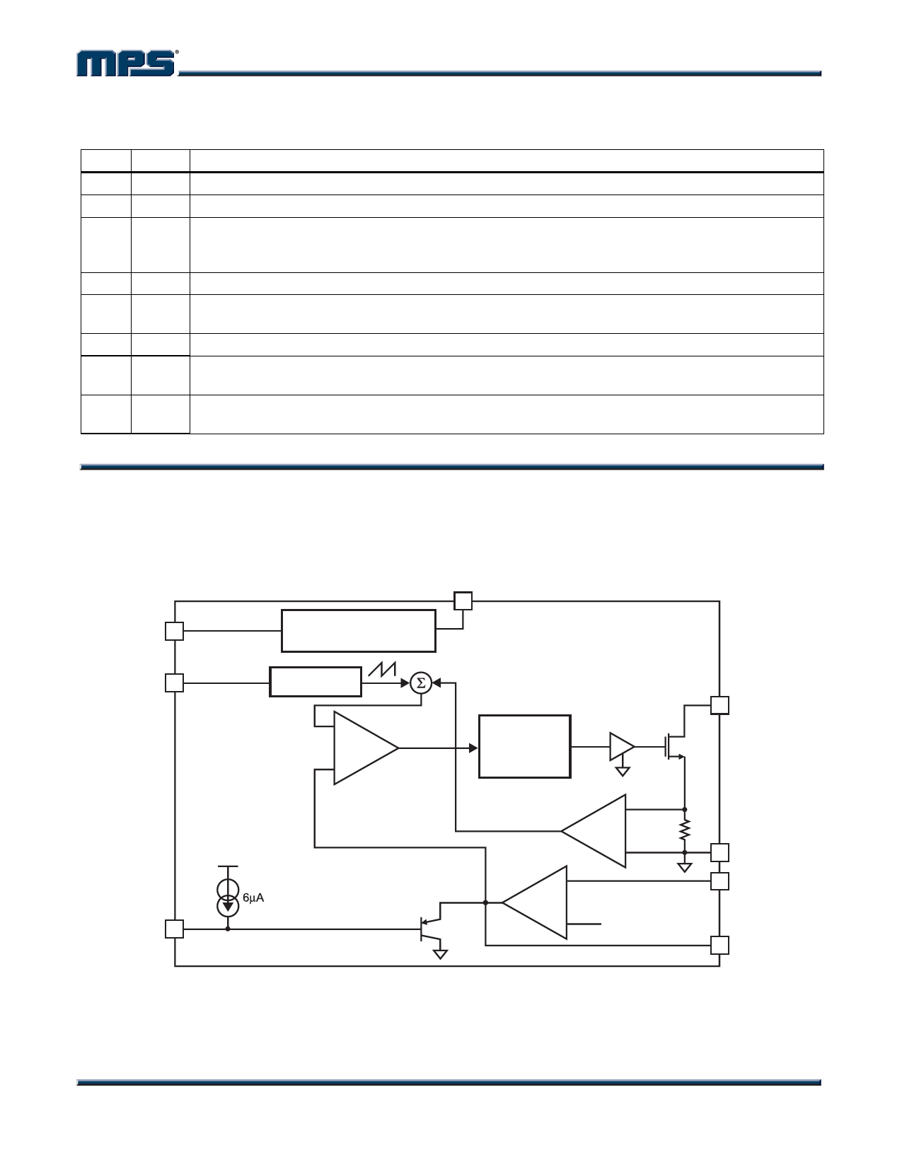
OPERATION
The MP3213 uses a constant frequency, peak
current mode boost regulation architecture to
regulate the feedback voltage.
The operation of the MP3213 can be
understood by referring to the block diagram of
Figure 1.
IN
EN
INTERNAL REGULATOR
AND ENABLE CIRCUITRY
FSEL
SS
OSCILLATOR
+
--
PWM
CONTROL
LOGIC
CURRENT
SENSE
+
AMP
--
GM
+
--
1.25V
Figure 1—Functional Block Diagram
SW
GND
FB
COMP
MP3213 Rev. 1.1
www.MonolithicPower.com
5
5/12/2006
MPS Proprietary Information. Unauthorized Photocopy and Duplication Prohibited.
© 2006 MPS. All Rights Reserved.
Share Link: 