NJU6624CFG1 데이터 시트보기 (PDF) - Japan Radio Corporation
부품명
상세내역
일치하는 목록
NJU6624CFG1
Japan Radio Corporation

NJU6624CFG1 Datasheet PDF : 27 Pages
| |||
NJU6624C
(2)Power on Initialization by internal circuits
(2-1)Initialization By Internal Reset Circuits
The NJU6624C is automatically initialized by internal power on initialization circuits when
the power is turned on. In the internal power on initialization, following instructions are executed. During the
Internal power on initialization, the busy flag (BF) is "1" and this status is kept 1.5ms (fosc=145kHz) after VDD
rises to 2.4V. Initialization flow is shown below:
Display ON/OFF control
Entry mode set
D=0 :Display Off
M=0 :Icon Off
B=0 :Cursor Blink Off
I/D=1 :Increment by 1
S=0 :No Shift
Set static port
P3-P0=0000 :All static port output signal is ”L”.
Contrast control
Set Display mode
Clear Display
E.V.R. Value=0000 : VLCD Low
K=1
DF=0
Keyscan ON
Release the power down mode
AC=00H
End
Note : If the condition of power supply rise time described in the Electrical Characteristics is not satisfied, the
internal Power On Initialization Circuits will not operated and initialization will not performed.
In this case the initialization by MPU software is required.
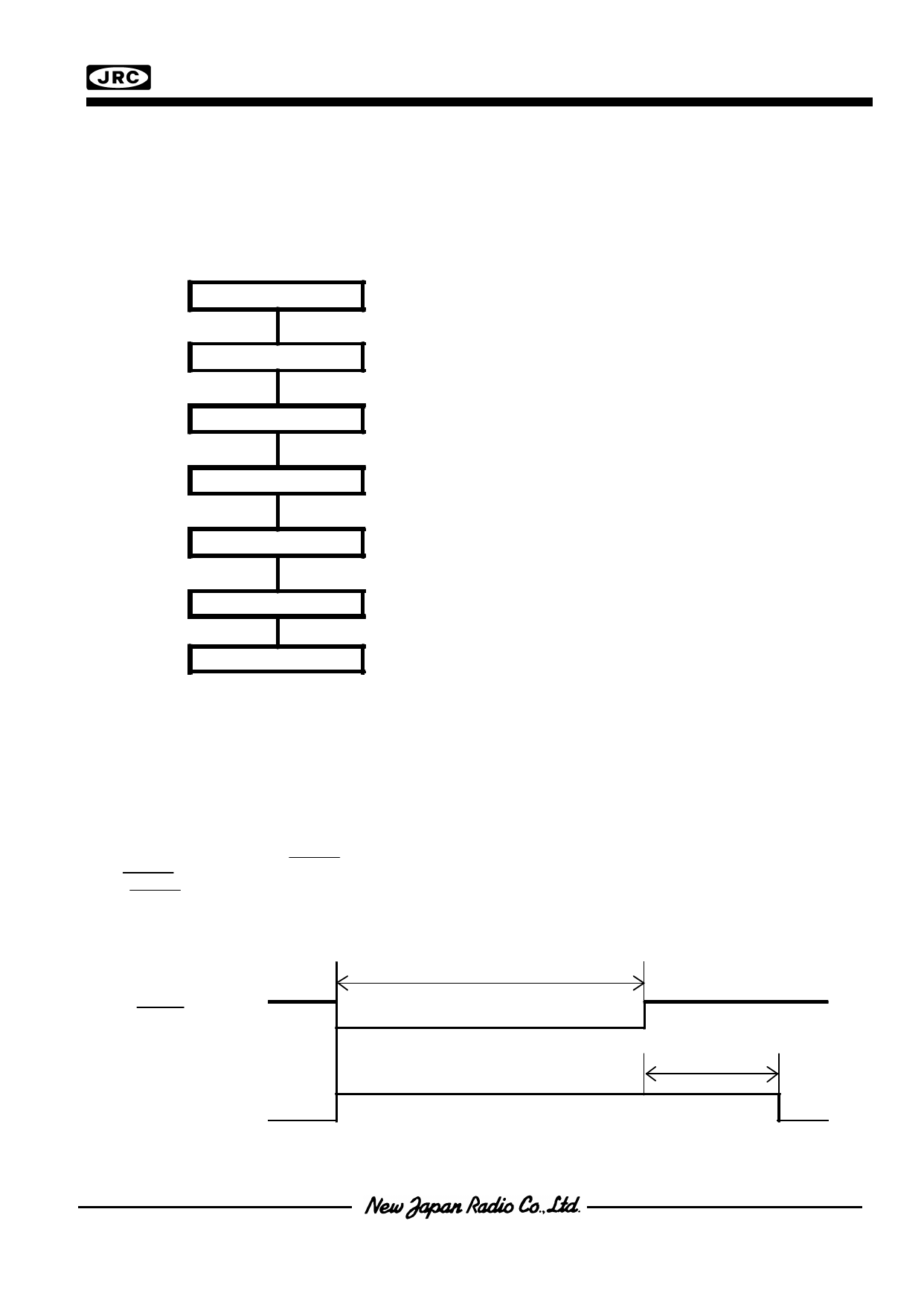
(2-2)Initialization By Hardware
The NJU6624C incorporates RESET terminal to initialize the all system. When the "L" level input over 1.2ms to
the RESET terminal, reset sequence is executed. In this time, busy signal output during 250us (fosc=145kHz)
after RESET terminal goes to "H". During this 250us period, any other instruction must not be input to the
NJU6624C.
-Timing Chart
External
RESET Signal
Over 1.2ms
Busy
250us
Share Link: