NJM3717E2 데이터 시트보기 (PDF) - Japan Radio Corporation
부품명
상세내역
일치하는 목록
NJM3717E2 Datasheet PDF : 10 Pages
| |||
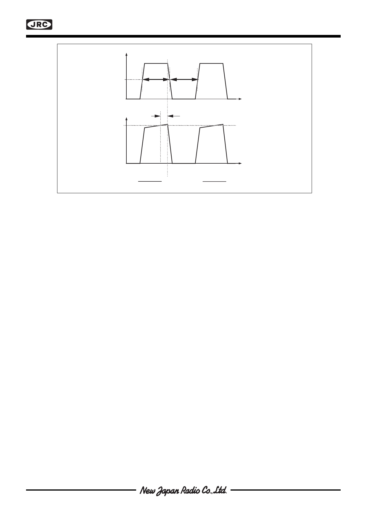
| V MA – VMB |
50 %
t on
t off
VE
td
V
CH
NJM3717
t
fs =
1
ton + toff
Figure 3. Definition of terms
t
D=
ton
ton + toff
s FUNCTIONAL DESCRIPTION
The NJM3717 is intended to drive a bipolar constant current through one motor winding of a 2-phase stepper
motor.
Current control is achieved through switched-mode regulation, see figure 4 and 5.
Three different current levels and zero current can be selected by the input logic.
The circuit contains the following functional blocks:
• Input logic
• Current sense
• Single-pulse generator
• Output stage
Input logic
Phase input. The phase input determines the direction of the current in the motor winding. High input forces the
current from terminal M to M and low input from terminal M to M . A Schmitt trigger provides noise immunity and
A
B
B
A
a delay circuit eliminates the risk of cross conduction in the output stage during a phase shift.
Half- and full-step operation is possible.
Current level selection. The status of I0 and I1 inputs determines the current level in the motor winding. Three fixed
current levels can be selected according to the table below.
Motor current
High level
I0
I1
100% L L
Medium level
60% H L
Low level
20% L H
Zero current
0% H H
The specific values of the different current levels are determined by the reference voltage VR together with the value
of the sensing resistor RS.
The peak motor current can be calculated as follows:
im = (VR • 0.083) / RS [A], at 100% level
im = (VR • 0.050) / RS [A], at 60% level
im = (VR • 0.016) / RS [A], at 20% level
The motor current can also be continuously varied by modulating the voltage reference input.
Share Link: 