NJM3717E2 데이터 시트보기 (PDF) - Japan Radio Corporation
부품명
상세내역
일치하는 목록
NJM3717E2 Datasheet PDF : 10 Pages
| |||
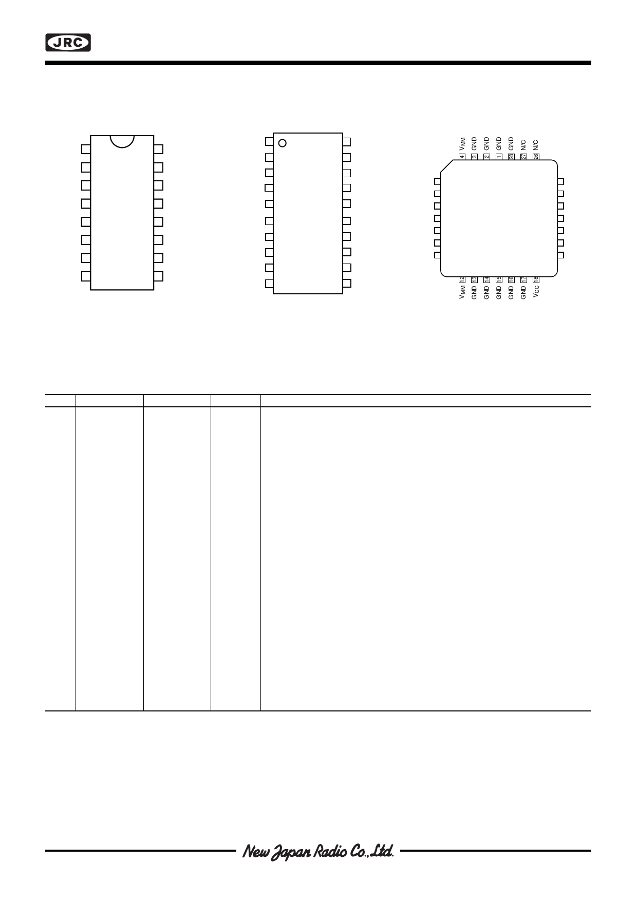
s PIN CONFIGURATIONS
NJM3717
MB 1
16 E
T2
15 MA
VMM 3
GND 4
GND 5
14 VMM
NJM 13 GND
3717D2 12 GND
VCC 6
11 VR
I1 7
10 C
Phase 8
9 I0
MB 1
T2
VMM 3
GND 4
GND 5
GND 6
GND 7
VCC 8
I1 9
Phase 10
NJM
3717E2
20 E
19 MA
18 VMM
17 GND
16 GND
15 GND
14 GND
13 VR
12 C
11 I 0
N/C 5
MA 6
N/C 7
E8
GND 9
MB 10
T 11
NJM3717FM2
25 N/C
24 VR
23 C
22 N/C
21 I 0
20 Phase
19 I1
Figure 2. Pin configurations
s PIN DESCRIPTION
DIP
EMP
1
1
2
2
PLCC
10
11
3,14
4,5,
12,13
3,18
4,5,6,7,14
15,16,17
12,4
1,2,3,9,13,
14,15,16,17
28
6
8
18
7
9
19
8
10
20
9
11
21
10
12
23
11
13
24
15
19
6
16
20
8
Symbol
M
B
T
VMM
GND
V
CC
I1
Phase
I
0
C
VR
MA
E
Description
Motor output B, Motor current flows from M to M when Phase is high.
A
B
Clock oscillator. Timing pin connect a 56 kΩ resistor and a 820 pF in
parallel between T and Ground.
Motor supply voltage, 10 to 45 V. VMM pins should be wired together on
PCB.
Ground and negative supply. Note these pins are used for heatsinking.
Make sure that all ground pins are soldered onto a suitable large copper
ground plane for efficient heat sinking.
Logic voltage supply normally +5 V.
Logic input, it controls, together with the I0 input, the current level in the
output stage. The controllable levels are fixed to 100, 60, 20, 0%.
Controls the direction of the motor current of MA and MB outputs. Motor
current flows from MA to MB when the phase input is high.
Logic input, it controls, together with the I input, the current level in the
1
output
stage. The controlable levels are fixed to 100, 60, 20, 0%.
Comparator input. This input senses the instantaneous voltage across the
sensing resistor, filtered through a RC Network.
Reference voltage. Controls the threshold voltage of the comparator and
hence the output current. Input resistance: typically 6.8kΩ ± 20%.
Motor output A, Motor current flows from MA to MB when Phase is high.
Common emitter. Connect the sense resistor between this pin and ground.
Share Link: 