CH1787 데이터 시트보기 (PDF) - Cermetek Microelectronics
부품명
상세내역
일치하는 목록
CH1787 Datasheet PDF : 14 Pages
| |||
Cermetek Microelectronics, Inc.
Table 3. CH1787 AT Command Set Summary.
Basic
Commands Function
AT
Attention Code
A
Answer Command
A/
Repeat Last Command
*Bn
Communications Standard Option
D
Dial Command
*E
Off-Line Character Echo Option
Hn
Switch Hook Control Option
*Ln
Speaker Volume Option
*Mn
Speaker Control Option
On
On-Lone Command
P
Pulse Dial
*Qn
Result Code Display Option
Sn
Select an S Register
Sn=
Write to an S Register
Sn?
Read an S Register
*Vn
Result Code From Option
*Xn
Result Code Set/Call Progress Option
+++
Escape Code Sequence
,
Pause
?
Returns Last Addressed S Register
*Yn
Long Space Disconnect Option
Fn
On-Line Echo Character Option
Z
Reset
Ampersand
Commands Function
*&Dn Data Terminal Ready Option
&F
Load Factory Defaults
*&Gn Guard Tone Option
*&Pn Make to Break Ratio Selection
*&Sn Data Set Ready Option
&Tn
Test Command Option
&V
View Active Configuration
*&Wn Store Active Profile
*Yn
Recall Active Profile
*&Zn
Store Telephone Numbers
*&Cn Not Supported
Percent
Commands Function
%Dn
DTMF Attenuation
%J
Load Secondary Factory Defaults
*= Commands that can be stored in NVRAM.
NOTE: Refer to Cermetek Publication AT Commands
and S-Registers for a detailed discussion of
parameters in Table 2 and 3.
Two of these lines are all that are required for proper
CH1787 operation: TXD, RXD and DTR. The modem
is controlled by sending it serial commands over TXD
and can be monitored by serial status messages
returned on RXD.
All other serial interface lines may be utilized for the
convenience of your application but are not required by
the modem. Unused outputs (form modem) should be
CH1787 Small Footprint Hardware Controllable 2400bps Modem
left unconnected. Unused inputs should be tied to the
proper logic level. See pin description.
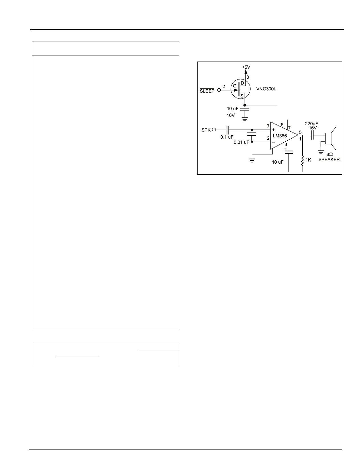
Figure 5. Speaker Control. Circuit allows call
progress monitoring.
PHONE LINE CONNECTION GUIDELINES
1. The mounting of CH1787 in the final assembly
must be made so that it is isolated from exposure to
any hazardous voltages within the assembly.
Adequate separation and restraint of cables and
cords must be provided.
2. The circuitry from the CH1787 to the telephone line
interface must be provided in wiring that carries no
other circuitry than that specifically allowed in the
rules (such as A and A1 leads).
3. Connection to phone line should be made through
an RJ-11 jack.
4. Traces from the modem’s RING and TIP pins to the
RJ-11 jack must exceed 0.1 inch spacing to one
another and 0.2 inch spacing to all other traces.
The traces should have a nominal width of 0.020
inches or greater.
5. The RING and TIP traces should be as short as
possible and oriented to prevent coupling other
high speed or high frequency signals onto the host
circuit card.
6. No additional circuitry other than that shown in the
following Figure may be connected between the
modem module and RJ-11 jack.
7. The CH1787, the RJ-11 jack, the interfacing
circuitry and traces in between, must be mounted
on a circuit board with a 94 V-0 flammability rating.
8. The supplied FCC registration label must be
applied visibly on the outside of the host product.
2002 Cermetek Microelectronics, Inc.
Page 8
Document No. 607-0002 Revision B (03/02)
Share Link: 