CH1787 데이터 시트보기 (PDF) - Cermetek Microelectronics
부품명
상세내역
일치하는 목록
CH1787 Datasheet PDF : 14 Pages
| |||
Cermetek Microelectronics, Inc.
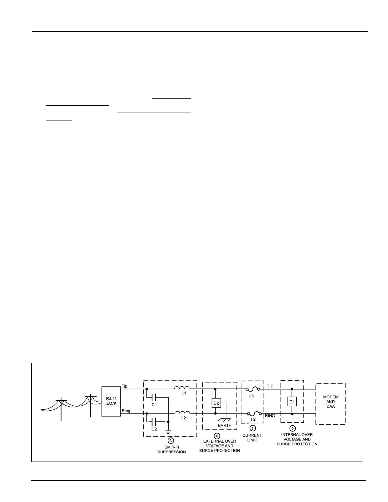
PSTN PROTECTION REQUIREMENTS
1. Currently Limiting PSTN Protection Line Device.
Currently limiting devices are mandatory to meet
UL safety standards. To maintain conveyed FCC
Part 68 approval, the current limiting components
identified as F1 and F2 in dashed Box #1 must also
survive FCC Part 68 surge testing. Refer to
Cermetek Application Note #126, Supplemental
PSTN Line Protection, for more details. Refer to
Application Note # 130, Summary of Recommend
Suppliers, for a list of suppliers and associated part
numbers.
A. A PTC (rated at 0.15 amps) is preferred
because it resets automatically upon removal of
the current flow. Non-resettable devices are
also acceptable. Refer to Application Note
#130 for a complete list of recommended
vendors and associated part numbers.
B. Resistors (10Ω carbon film or 1/8 watt
minimum) may be used in Canada, as Canada
has no requirements that PSTN equipment be
operational after a Type B surge test.
C. Although CSA CS-03 Part 1 (Canada) follows
the requirements of FCC Part 68 (USA),
Cermetek recommends contacting DOT
(Canada) and/or a certified independent lab to
verify compliance. For Canada, use either 10Ω
resistors (carbon film or SMD parts 1/8 watt
minimum) as described in paragraph B above.
2. Over Voltage and Lightning Protection.
A. Surge Protection is provided by internal
circuitry (see Figure 3). No additional external
components are required to maintain conveyed
FCC Part 68 approval.
CH1787 Small Footprint Hardware Controllable 2400bps Modem
B. In most environments, 2 terminal surge
suppressors are adequate. For severe
environments, use an external 3 terminal
device with an earth ground.
3. EMI/RFI Suppression.
No external EMI/RFI noise suppression circuitry is
required to maintain conveyed FCC Part 68
approval. However, additional suppression, if
required for other reasons, may be added as
described below in Sections 3A-3B without
adversely affecting FCC Part 68 approval.
A. To provide adequate EMI/RFI suppression, the
capacitor/inductor network contained in dashed
Box #3 should be located as close to the RJ11
Jack as possible. Further, this network should
be provided with an excellent ground path to
the chassis.
B. Capacitors C1 and C2 should not exceed
0.005µf. They must have a rating of 1.5KV and
typically are 0.001µf ± 20%. Inductors L1 and
L2 may be either individual inductors or a dual
inductor. Refer to Application Note #130 for a
complete list of recommended vendors and
associated part numbers. For UL applications,
choose capacitors and inductors that are UL
1950 listed. The actual values of the
components used may vary depending on the
end product design.
Figure 6. Telephone Interfaces.
2002 Cermetek Microelectronics, Inc.
Page 10
Document No. 607-0002 Revision B (03/02)
Share Link: 