CH1787(1998) 데이터 시트보기 (PDF) - Cermetek Microelectronics
부품명
상세내역
일치하는 목록
CH1787 Datasheet PDF : 13 Pages
| |||
POWER SUPPLY
The modem module is a complex sub-system that may be treated
as any other component. Special attention should be paid to the
power supply connections. The modem decodes analog signals
from the telephone line that are in the millivolt range. Al though the
modem is designed to withstand significantly induced power sup-
ply noise, there is a limit. Steps must be taken to guarantee that
power supply noise on all supply lines, including ground, does not
exceed 50 mV peak to peak. Any frequency between 20 kHz and
150 kHz must be less than 50 mV peak. If necessary, use dedi-
cated power and ground planes. Failure to provide such operating
conditions could cause the modem to malfunction.
The CH1787requires a single +5V ±5% supply. It is recommended
that by-pass capacitors be placed on the power supply as close to
the modems supply input as practical. It is recommended that a
10 µF Electrolytic capacitor in parallel with a 0.01µF ceramic
capacitor be used.
WARNING: The CH1787 has been FCC Part 68 approved as a
data modem. Utilization of the Voice/Tone Port requires further
registration. FCC will require that the system, including the CH1787
and the handset or DTMF transceiver, adhere to Part 68 rules.
MODEM CONTROL
The CH1787 modem may be controlled by sending serial ASCII
command sequences. The commands are sent to the modem
serially on TXD. After execution of the command, the modem re-
turns a serial status message on RXD, to indicate the completion
status of the command.
Initializing the Modem
Before commands may be sent to the modem, the modem must
be initialized. This consists of two events: 1) after power-up, a
hardware reset pulse must be applied to the modem, and 2) the
modem must be trained to the hosts speed (2400, 1200, 300bps)
and parity (odd, even, mark, space or none).
ENABLE RXA 4.7K
MECHANICAL RELAY ONLY.
A ZERO IMPEDANCE SWITCH MAY REPLACE
THE RELAY AND TRANSISTOR CIRCUIT.
+5V
+15V
2N2222
1N914
20K
20K
0.1uF
0.1uF
3
+ 41
A
2
-
TL064
82K
20K
VOICE OR DTMF
SIGNAL
499 B
0.1uF
63.4K
20K
A1 54K
2.2uF
nonpolar
1 RING
2 TIP
CH1787
7 RXA
8 DTR
9 ANS
10 V/D
11 RST
12 RI
13 CTS
14 DSR
15 DRA
16 TXD
17 DIR
AAR 34
GND 33
VCC 32
RXD 31
HNG 30
CON 29
TST 28
SPKR 27
NC 26
NC 25
NC 24
DAG 23
HS 22
18 IRQ
DCD 21
19 SLEEP
GND 20
0.1uF
6
7
-
5
11 +
TL064
28K
A2
0.1uF
ADJUST A2 FOR THE DESIRED LEVEL OF AXT VOICE TO BE ECHOED TO AXR.
DECREASE RECEIVE GAIN SIGNAL. AXR. BY DECREASING VALUE OF A1.
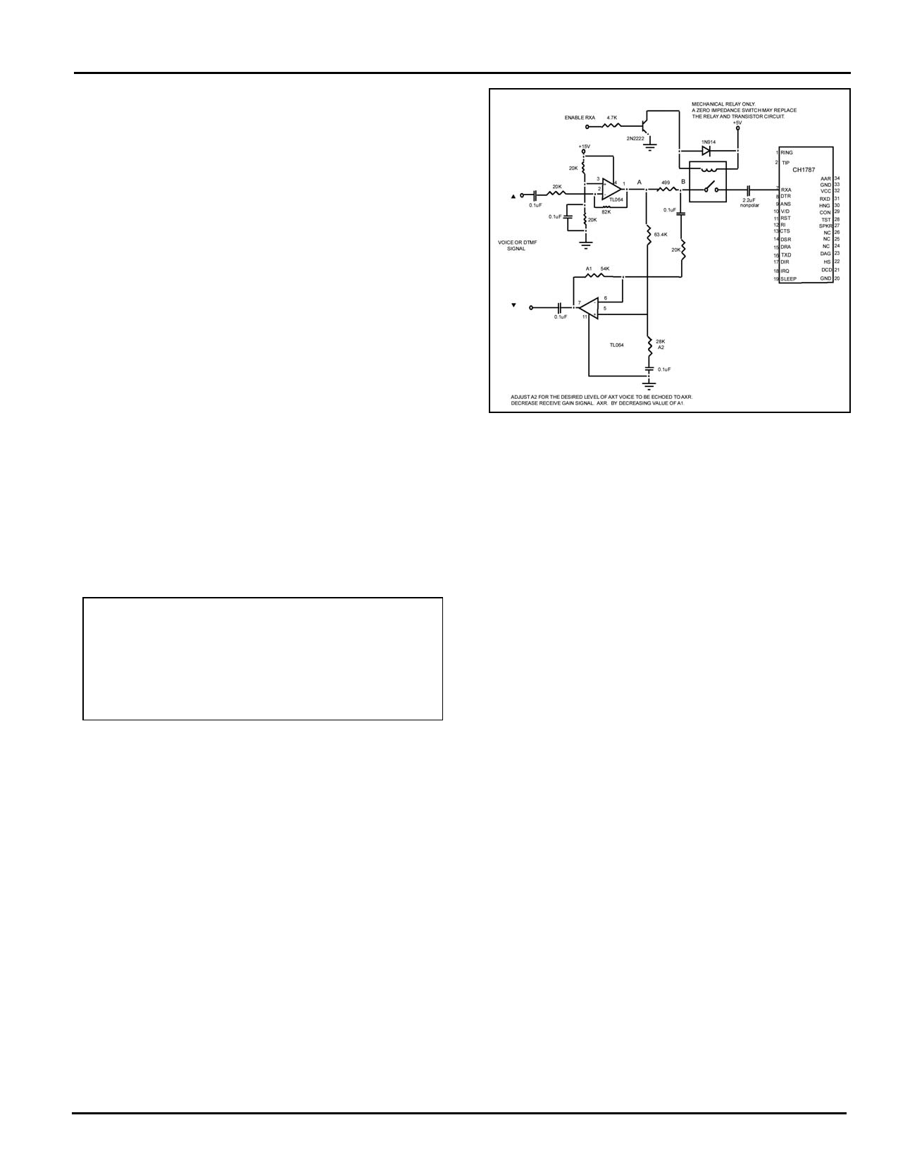
Figure 3. Voice/Tone Injection
Power-up Reset
After applying power to the modem, an internally generated reset
pulse is created. The user can also reset the modem externally by
applying the high-going reset pulse to RST for at least 10ms after
the +5V power supply has stabilized. Delay sending commands
to CH1787 for 100-200ms.
Training the Modem
The modem must be trained to match the hosts speed and parity
so that it is able to recognize serial asynchronous commands
sent to it by the host UART. The host must retrain the modem each
time a reset signal is applied on RST or after a RESET serial
command. The modem is trained by sending it the following three-
character sequence.
Figure 4. CH1787 Application Diagram of Test Circuit
Cermetek Microelectronics, Inc.
RI
FROM 1787
PIN 12
10K
.1uF
10K
+Vcc
+Vcc
3+
8
1
LM393
2
4
+
4.7uF
+Vcc
22K
5+
7
LM393
6
4.7K
ISOLATED
ENVELOPE
RING DETECT
Document No. 603-0182 Rev. D (11/98) 3
Share Link: 