HSP9501 데이터 시트보기 (PDF) - Intersil
부품명
상세내역
일치하는 목록
HSP9501 Datasheet PDF : 8 Pages
| |||
HSP9501
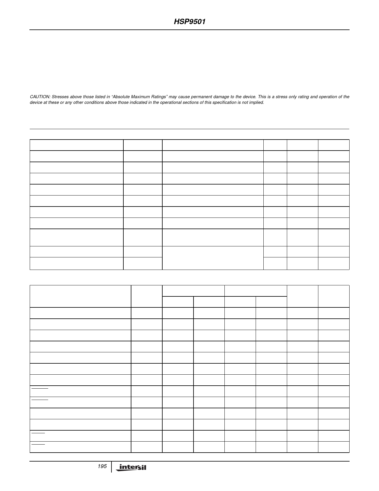
Absolute Maximum Ratings
Supply Voltage . . . . . . . . . . . . . . . . . . . . . . . . . . . . . . . . . . . . . +8.0V
Input, Output or Voltage Applied . . . . . . . .GND -0.5V to VCC +0.5V
Operating Conditions
Temperature Range . . . . . . . . . . . . . . . . . . . . . . . . . . . .0oC to 70oC
Voltage Range . . . . . . . . . . . . . . . . . . . . . . . . . . . . +4.75V to 5.25V
Thermal Information
Thermal Resistance (Typical, Note 1)
θJA (oC/W)
PLCC Package. . . . . . . . . . . . . . . . . . . . . . . . . . . . .
45.2
Maximum Junction Temperature . . . . . . . . . . . . . . . . . . . . . . .150oC
Maximum Storage Temperature Range . . . . . . . . . . -65oC to 150oC
Maximum Lead Temperature (Soldering 10s) . . . . . . . . . . . . .300oC
(PLCC - Lead Tips Only)
CAUTION: Stresses above those listed in “Absolute Maximum Ratings” may cause permanent damage to the device. This is a stress only rating and operation of the
device at these or any other conditions above those indicated in the operational sections of this specification is not implied.
NOTE:
1. θJA is measured with the component mounted on an evaluation PC board in free air.
DC Electrical Specifications VCC = 5.0V +5%, TA = 0oC to 70oC, Commercial
PARAMETER
SYMBOL
TEST CONDITIONS
MIN
MAX
UNITS
Logical One Input Voltage
Logical Zero Input Voltage
Output HIGH Voltage
Output LOW Voltage
Input Leakage Current
Output Leakage Current
Standby Current
Operating Power Supply Current
Input Capacitance
Output Capacitance
VIH
VCC = 5.25V
2.0
-
V
VIL
VCC = 4.75V
-
0.8
V
VOH
IOH = -4mA VCC = 4.75V
2.4
-
V
VOL
IOL = +4.0mA VCC = 4.75V
-
0.4
V
II
VIN = GND or VCC VCC = 5.25V
-10
10
µA
IO
VOUT = GND or VCC = 5.25V
-10
10
µA
ICCSB
VIN = VCC or GND, VCC = 5.25V, Note 3
-
500
µA
ICCOP
f = 25MHz, VIN = VCC or GND
VCC = 5.25V, Notes 2, 3
-
125
mA
CIN
FREQ = 1MHz, VCC = Open, All
-
10
pF
measurements are referenced to device
CO
GND
-
10
pF
AC Electrical Specifications VCC = 5.0V ±5%, TA = 0oC to +70oC, Commercial, (Note 5)
-32
-25
PARAMETER
SYMBOL
MIN
MAX
MIN
MAX
Clock Period
Clock Pulse Width High
Clock Pulse Width Low
Data Input Setup Time
Data Input Hold Time
Output Enable Time
Output Disable Time
CLKEN to Clock Setup
CLKEN to Clock Hold
LC0-10 Setup Time
LC0-10 Hold Time
LCEN to Clock Setup
LCEN to Clock Hold
t CP
31
-
40
-
t PWH
12
-
15
-
t PWL
12
-
-
15
t DS
10
-
12
-
t DH
2
-
2
-
t ENA
-
20
-
25
t DIS
-
24
-
25
t ES
10
-
12
-
t EH
2
-
2
-
t LS
10
-
13
-
t LH
2
-
2
-
t LES
10
-
13
-
t LEH
2
-
2
-
UNITS
ns
ns
ns
ns
ns
ns
ns
ns
ns
ns
ns
ns
ns
NOTES
-
-
-
-
-
-
Note 4
-
-
-
-
-
-
195
Share Link: 