LT1509 데이터 시트보기 (PDF) - Linear Technology
부품명
상세내역
일치하는 목록
LT1509 Datasheet PDF : 16 Pages
| |||
LT1509
APPLICATIONS INFORMATION
VAOUT = 2 +
(PIN)(RS)(25)(RIAC + 25k)
(VIN2)(RREF)
See Figure 2 for RREF.
VAOUT is squared in the multiplier, resulting in excellent
performance over a wide range of output power and input
voltage without the addition of feedforward line frequency
ripple. Care must be taken to avoid feeding switching
frequency noise into the multiplier from the IAC pin. An
internal 25k is provided in series with the low impedance
multiplier input so that only a capacitor from the IAC pin to
GND1 is required to filter noise. The maximum multiplier
output current, which ultimately limits the input line cur-
rent, is set by a resistor from the RSET pin to GND1
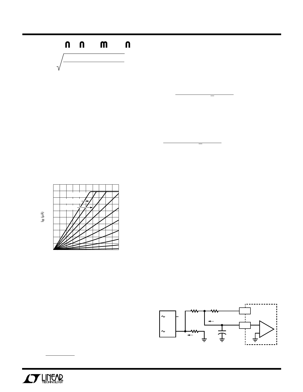
according to the formula: IM(MAX) = 3.75V/RSET. Figure 5
shows IM versus IAC for various values of VAOUT. Note that
Figure 5 data was taken with RSET = 15k.
300
VAOUT = 7V
VAOUT = 6.5V
VAOUT = 6V
150
VAOUT = 5.5V
VAOUT = 5V
VAOUT = 4.5V
VAOUT = 4V
VAOUT = 3.5V
VAOUT = 3V
0
VAOUT = 2.5V
0
250
500
IAC (µA)
LT1509 • F05
Figure 5. Multiplier Current IM vs IAC and VAOUT
Oscillator Frequency and Maximum
Line Current Setting
The oscillator frequency is set by RSET and CSET. RSET is
the resistor from the RSET pin to GND1 and CSET is the
capacitor from the CSET pin to GND1. RSET should be
determined first. The oscillator frequency, which is equal
to the switching frequency for both the PFC and PWM
section, is determined by:
fOSC
=
1.5
(RSET)(CSET)
The multiplier output acts as the command signal to the
current loop error amplifier. During steady-state operation
the voltage across RREF = (IM)(RREF) = (IIN)(RS). Based on
this the value for RS is determined by:
RS
≤
(IM(MAX))(RREF)(VIN)(eff)
POUT √2
with RSET = 15k, IM(MAX) = 3.75/15k = 250µA. For a 300W
converter with an efficiency (eff) of 0.8 at low line (90VRMS)
and RREF set to 4k, RS should be less than:
(250µA)(4k)(90VAC)(0.8) = 0.169Ω
300W√2
A 0.15Ω resistor will yield a maximum peak input current
of (IM(MAX))(RREF/RS) = (250µA)(4k)/0.15Ω = 6.67A. For
a 100kHz switching frequency with RSET = 15k, CSET = 1.5/
(100kHz)(15k) = 1nF. For added protection the LT1509
provides a second independent current limit comparator.
When the input voltage to the comparator (PKLIM pin) dips
below 0V, GTDR1 pin quickly goes low turning off the PFC
power switch. A resistor divider from VREF to RS (Figure 6)
senses the voltage across the line current sense resistor
(RS) and limits the peak input line current to [(7.5V/R1) +
50µA] (R2/RS). The 50µA represents the PKLIM input
current which flows out of the PKLIM pin. With R1 = 10k
and R2 = 1.8k, IIN = 9.6A peak above the 6.67A peak
average plus the input inductor peak ripple current.
Always use RSET to set the primary line current limit. The
PKLIM comparator is only for secondary protection. When
the line current reaches the primary limit, VOUT can no
longer be supported with the given input current and
begins to fall. System stability is maintained by the current
loop which is controlled by the current amplifier. When the
R2
R1
1.8k
10k
7.5V
VREF
LT1509
+
RS
0.15Ω
IPKLIM
PKLIM
–
–
C1
ILINE
1nF
+
C1 IS TO REJECT NOISE, CURRENT
LIMIT DELAY IS ABOUT 2µs
Figure 6
LT1509 • F06
9
Share Link: 