DRS-DTH(2017) 데이터 시트보기 (PDF) - Littelfuse, Inc
부품명
상세내역
일치하는 목록
DRS-DTH Datasheet PDF : 2 Pages
| |||
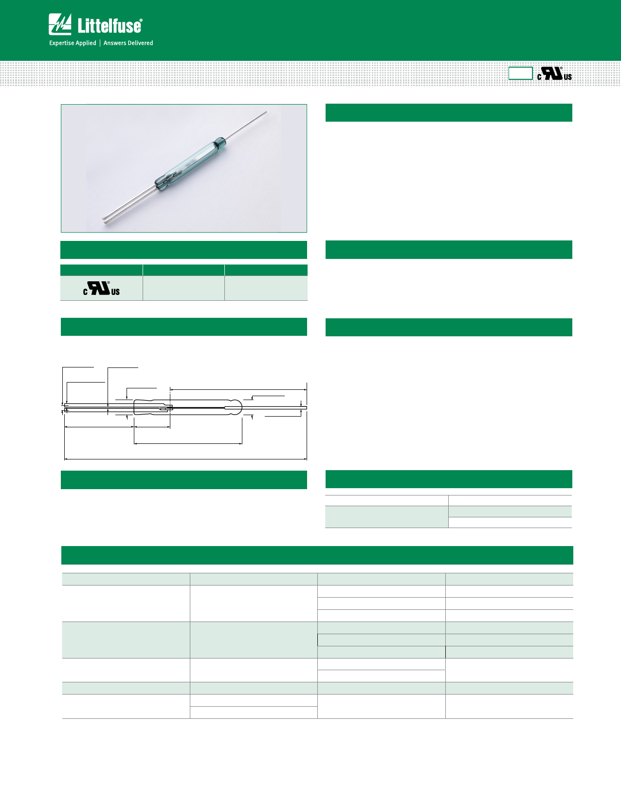
Axial Lead Reed Switches
High Power > DRS-DTH
DRS-DTH 39.7mm Standard Changeover Reed Switch
RoHS
Description
The DRS-DTH Reed Switch is a large changeover switch with a 39.67mm long x
5.33mm diameter (1.562” x 0.210”) glass envelope, capable high voltage and
power switching up to 500Vdc at 2mA, or 0.5A up to 30W/VA. The DRS-DTH has
an insulation resistance of 109 ohms minimum and contact resistance of less than
Dimensions
Dimensions in mm (inch)
1.83
(.072) NOM.
0.25
(.010) NOM.
1.27
(.050) DIA. REF.
5.54 CL OF OVERLAP
(.218) MAX.
27.66
(1.89) REF.
5.33
(.210) MAX.
25.40
(1.000) NOM.
12.45
(.490) NOM.
38.10 - 39.67
(1.500) NOM. - (1.562) MAX.
85.73 - 84.14
(3.375) NOM. - (3.3125) MIN.
1.02
(.040) DIA. REF.
125 milli-ohms.
Features
• Changeover switch
• Capable of switching 500Vdc or
0.5A at up to 30W
• Minimum voltage breakdown
Y 1200Vdc
Benefits
R • Hermetically sealed switch
contacts are not affected by and
have no effect on their external
environment
• Can be used as changeover or
A normally closed contact
Applications
• Security
IN • Limit switching
• Available sensitivity range
50-80 AT
• Capable of switching European
mains voltage
• Zero operating power required for
contact closure
• Industrial safety applications
• White goods applications
PRELIMSwitch Type
Electrical Ratings
Contact Form
Materials
C (SPDT-CO)
Body: Glass
Leads: Tin-plated Ni-Fe wire
Note: SPDT-CO = Single-Pole, Double-Throw, Change Over
Contact Rating 1
W/VA - max.
Voltage 3
Current 3
Switching 2
Breakdown 4
Switching 2
Carry
Vdc - max.
Vac - max.
Vdc - min.
Adc - max.
Aac - max.
Adc - max.
Resistance
Contact, Initial
Insulation
Ω - max.
Ω - min.
Capacitance
Contact
pF - typ.
Temperature
Operating
°C
Storage 5
°C
Notes:
1. Contact rating - Product of the switching voltage and current should never exceed the wattage rating. Contact Littelfuse for additional load/life information.
30
500
350
1200
0.50
0.35
3.0
0.125
109
2.0
-20 to +125
-65 to +125
2. When switching inductive and/or capacitive loads, the effects of transient voltages and/or currents should be considered. Refer to Application Notes AN108A and AN107 for details.
3. Electrical Load Life Expectancy - Contact Littelfuse with voltage, current values along with type of load.
4. Breakdown Voltage - per MIL-STD-202, Method 301.
5. Storage Temperature - Long time exposure at elevated temperature may degrade solderability of the leads.
© 2017 Littelfuse
Revised: 07/17/17
Specifications are subject to change without notice.
littelfuse.com
Share Link: 