SRK2000A 데이터 시트보기 (PDF) - STMicroelectronics
부품명
상세내역
일치하는 목록
SRK2000A Datasheet PDF : 19 Pages
| |||
Application information
SRK2000A
6.1.2
As VCC exceeds VCCOn, the internal current sink IEN is switched off and the enable function
is activated. The voltage on the pin is then compared to an internal reference VEN_On set at
1.8 V: if this threshold is exceeded the gate drivers GD1 and GD2 are enabled and the SR
MOSFET is operated; otherwise, the device stays in an idle condition and the SR MOSFET
in the off state.
Using the pull-up resistor RP, the voltage on the EN pin rises as IEN is switched off and tends
to VCC, therefore exceeding VEN_On and enabling the operation of both SR MOSFETs.
Essentially, this results in enabling the gate-driving as VCC exceeds VCCOn and disabling it
as VCC falls below VCCOn. This configuration is thereby recommended when SR MOSFETs
are logic level types.
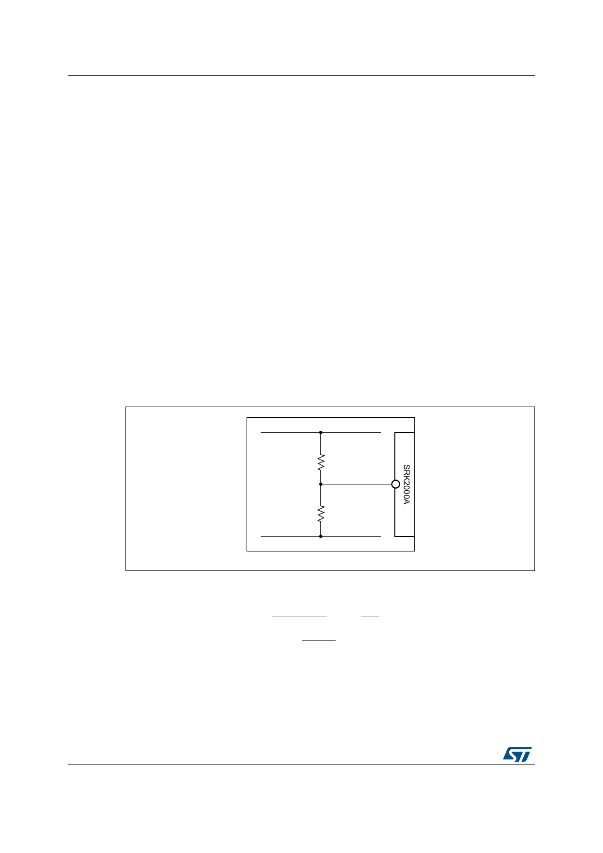
Resistor divider configuration
To enable gate-driving with a VCC voltage higher than a predefined value VCC_G, to properly
drive a standard SR MOSFET, the EN pin is biased by a resistor divider (R1 upper resistor,
R2 lower resistor) whose value is chosen so as to exceed VEN_On when VCC = VCC_G and
also to set the desired VDVS1,2_Off level. Note that, with a falling VCC, gate-driving is
disabled at a VCC level about 2.5% lower than VCC_G, because of the 45 mV hysteresis of
the comparator.
The equations that describe the circuit in the two crucial conditions VCC = VCCOn (when the
decision of the VDVS1,2_Off level is made) and VCC = VCC_G (when gate-driving is to be
enabled) are respectively:
Figure 6. EN pin biased with a resistor divider to program the gate drive UVLO
threshold VCC_G
9&&
5
(1
Equation 3
5
*1'
VVCCCC_ORGn 1R1VRE2NR2
IEN
VEN
R2
VEN _ On
$0
10/19
DocID025407 Rev 3
Share Link: 