CS8251 데이터 시트보기 (PDF) - ON Semiconductor
부품명
상세내역
일치하는 목록
CS8251 Datasheet PDF : 8 Pages
| |||
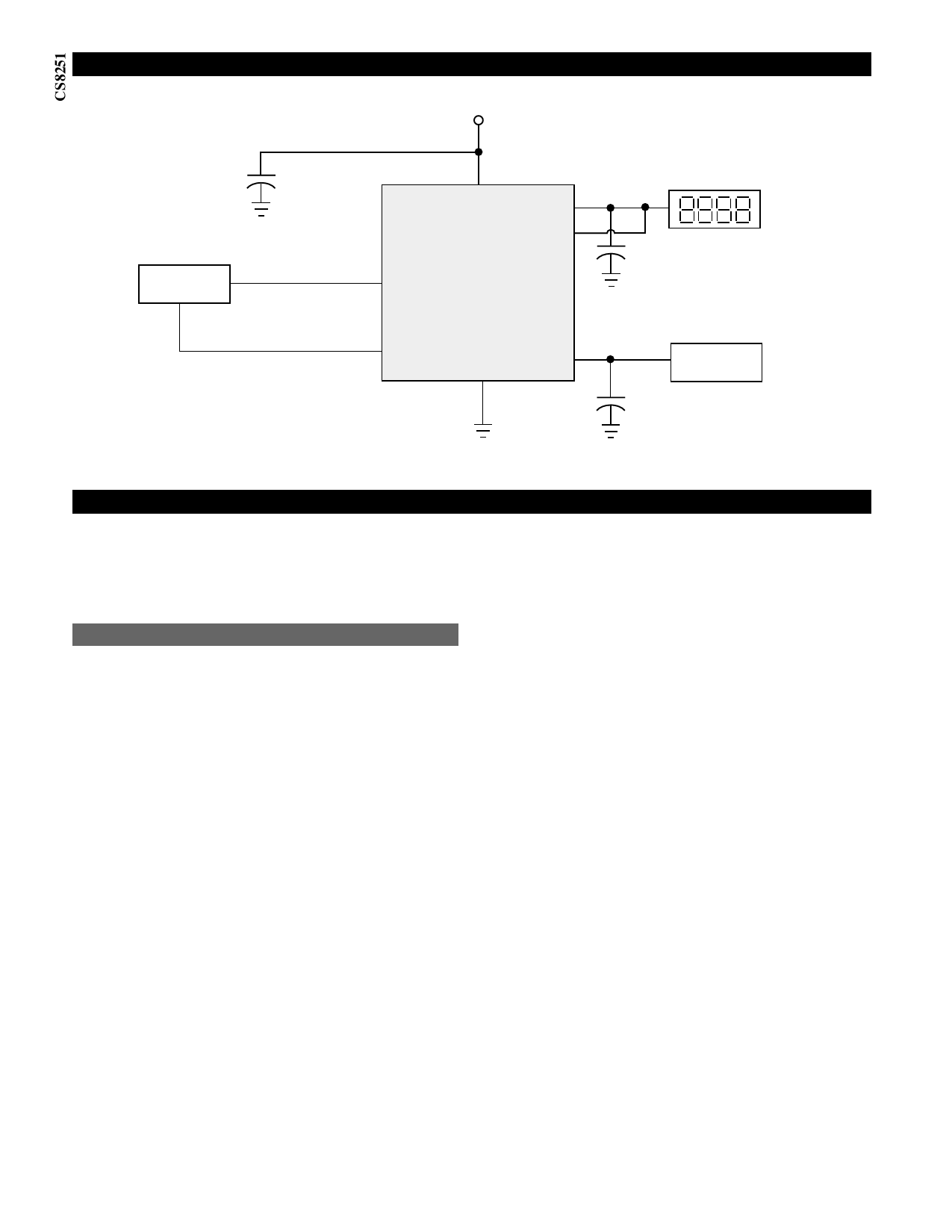
Applications Circuit
Control
C1*
0.1 µF
VIN
VOUT1
VOUT(SENSE)
CS8251
ENABLE1
DISPLAY
10V
C2** = 10µF
ENABLE2
Gnd
VOUT2
*C1 is required if regulator is far from power source filter.
**C2, C3 is required for stability
5V
Tuner IC
C3** = 10µF
Application Notes
With separate control of each output channel, the CS8251
is ideal for applications where each load must be switched
independently. In an automotive radio, the 10V output
drives the displays and tape drive motors while the 5V
output supplies the Tuner IC and memory.
Stability Considerations
The output or compensation capacitors determine three
main characteristics of a linear regulator: start-up delay,
load transient response and loop stability.
The capacitor values and types should be based on cost,
availability, size and temperature constraints. A tantalum
or aluminum electrolytic capacitor is best, since a film or
ceramic capacitor with almost zero ESR, can cause instabil-
ity. The aluminum electrolytic capacitor is the least expen-
sive solution, but, if the circuit operates at low tempera-
tures (-25°C to -40°C), both the value and ESR of the
capacitor will vary considerably. The capacitor manufac-
turers data sheet usually provide this information.
To determine acceptable values for the compensation
capacitors in a particular application, start with tantalum
capacitors of the recommended value and work towards a
less expensive alternative part on each output in turn.
Step 1: Place the completed circuit with tantalum capaci-
tors of the recommended values in an environmental
chamber at the lowest specified operating temperature
and monitor the outputs on the oscilloscope. A decade box
connected in series with one of the capacitors C2 or C3 will
simulate the higher ESR of an aluminum capacitor. (Leave
the decade box outside the chamber, the small resistance
added by the longer leads is negligible)
Step 2: With the input voltage at its maximum value,
increase the load current slowly from zero to full load
while observing the output for any oscillations. If no oscil-
lations are observed, the capacitor is large enough to
ensure a stable design under steady state conditions.
Step 3: Increase the ESR of the capacitor from zero using
the decade box and vary the load current until oscillations
appear. Record the values of load current and ESR that
cause the greatest oscillation. This represents the worst
case load conditions for the regulator at low temperature.
Step 4: Maintain the worst case load conditions set in step
3 and vary the input voltage until the oscillations increase.
This point represents the worst case input voltage condi-
tions.
Step 5: If the capacitor is adequate, repeat steps 3 and 4
with the next smaller valued capacitor. (A smaller capaci-
tor will usually cost less and occupy less board space.) If
the circuit oscillates within the range of expected operat-
ing conditions, repeat steps 3 and 4 with the next larger
standard capacitor value.
Step 6: Test the load transient response by switching in
various loads at several frequencies to simulate its real
work environment. Vary the ESR to reduce ringing.
Step 7: Remove the unit from the environmental chamber
and heat the IC with a heat gun. Vary the load current as
instructed in step 5 to test for any oscillations.
Once the minimum capacitor value with the maximum
ESR is found for each output, a safety factor should be
added to allow for the tolerance of the capacitor and any
variations in regulator performance. Most good quality
aluminum electrolytic capacitors have a tolerance of ±20%
so the minimum value found should be increased by at
least 50% to allow for this tolerance plus the variation
which will occur at low temperatures. The ESR of the
capacitors should be less than 50% of the maximum allow-
able ESR found in step 3 above.
Repeat steps 1 through 7 with the second output leaving a
large tantalum on the first output for stability.
4
Share Link: 