NJM2275F1 데이터 시트보기 (PDF) - Japan Radio Corporation
부품명
상세내역
일치하는 목록
NJM2275F1 Datasheet PDF : 11 Pages
| |||
NJM2275
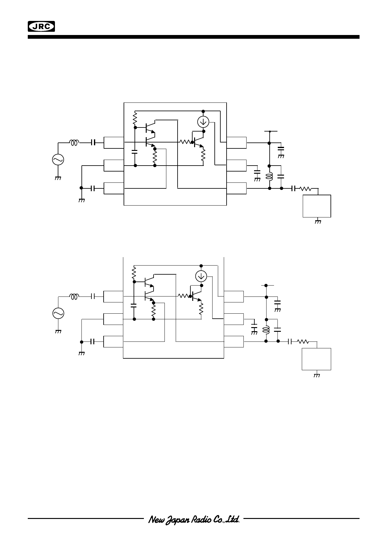
TEST CIRCUIT
These test circuits allow the measurement of all parameters described in “ELECTRICAL CHARACTERISTICS”.
Test Circuit 1 for Icc, PG , P–1dB and Pin vs. Pout
L in
27n
C in
1000p
RF IN
1
SG
(50Ω)
GND
2
Cb BIAS CAP
1000p
3
Test Circuit 2 for VG
V+
V+
6
I REF Cref
5
1000p
Cv
1000p
RF OUT
4
CL RL
2p 0Ω
Lout Cout
15n 8p
Spe ctr um
Analyz e r
(Zin=50Ω)
L in
27n
C in
1000p
RF IN
1
SG
(50Ω)
GND
2
Cb BIAS CAP
1000p
3
V+
V+
6
I REF Cref
1000p
5
Cv
1000p
RF OUT
4
CL RL
1000p 1kΩ
Lout Cout
27n 4p
Spe ctr um
Analyzer
(Zin=50Ω)
PG and VG has the following relation.
PG = Pout – Pin
VG = (Pout + Prl ) – Pin
where
Pin = input level in dBm
Pout = output level in dBm
Prl = the loss caused by the voltage drop of RL.
RL is 1000 Ω. The input impedance of spectrum analyzer Zin is 50Ω. Prl is calculated from
Prl = 20log ( ( RL + Zin) / RL)
Prl = 20 log (1050 / 50 )
Ver.2005-06-01
-3-
Share Link: 