ISL84581 데이터 시트보기 (PDF) - Renesas Electronics
부품명
상세내역
일치하는 목록
ISL84581 Datasheet PDF : 15 Pages
| |||
ISL84581
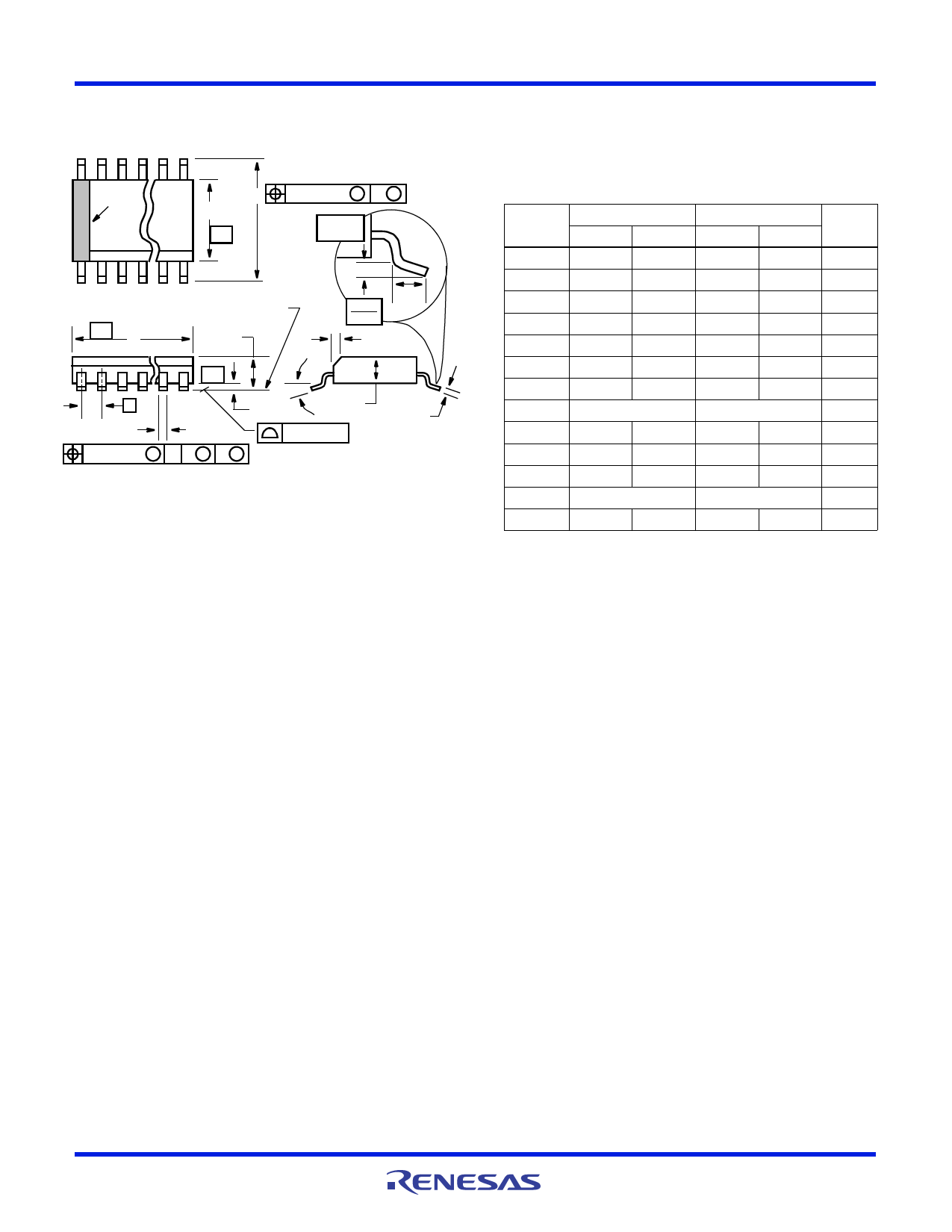
Shrink Small Outline Plastic Packages (SSOP)
Quarter Size Outline Plastic Packages (QSOP)
N
INDEX
AREA
H
E
-B-
0.25(0.010) M B M
GAUGE
PLANE
123
-A-
D
SEATING PLANE
A
L
0.25
0.010
h x 45°
-C-
e
A1
A2
C
B
0.10(0.004)
0.17(0.007) M C A M B S
NOTES:
1. Symbols are defined in the “MO Series Symbol List” in Section
2.2 of Publication Number 95.
2. Dimensioning and tolerancing per ANSI Y14.5M-1982.
3. Dimension “D” does not include mold flash, protrusions or gate
burrs. Mold flash, protrusion and gate burrs shall not exceed
0.15mm (0.006 inch) per side.
4. Dimension “E” does not include interlead flash or protrusions.
Interlead flash and protrusions shall not exceed 0.25mm (0.010
inch) per side.
5. The chamfer on the body is optional. If it is not present, a visual
index feature must be located within the crosshatched area.
6. “L” is the length of terminal for soldering to a substrate.
7. “N” is the number of terminal positions.
8. Terminal numbers are shown for reference only.
9. Dimension “B” does not include dambar protrusion. Allowable
dambar protrusion shall be 0.10mm (0.004 inch) total in excess
of “B” dimension at maximum material condition.
10. Controlling dimension: INCHES. Converted millimeter dimen-
sions are not necessarily exact.
M16.15A
16 LEAD SHRINK SMALL OUTLINE PLASTIC PACKAGE
(0.150” WIDE BODY)
INCHES
MILLIMETERS
SYMBOL MIN
MAX
MIN
MAX NOTES
A
0.061
0.068
1.55
1.73
-
A1
0.004
0.0098 0.102
0.249
-
A2
0.055
0.061
1.40
1.55
-
B
0.008
0.012
0.20
0.31
9
C
0.0075 0.0098 0.191
0.249
-
D
0.189
0.196
4.80
4.98
3
E
0.150
0.157
3.81
3.99
4
e
0.025 BSC
0.635 BSC
-
H
0.230
0.244
5.84
6.20
-
h
0.010
0.016
0.25
0.41
5
L
0.016
0.035
0.41
0.89
6
N
16
16
7
0°
8°
0°
8°
-
Rev. 2 6/04
FN6416 Rev 3.00
April 13, 2009
Page 14 of 15
Share Link: 