ISL6557A 데이터 시트보기 (PDF) - Renesas Electronics
부품명
상세내역
일치하는 목록
ISL6557A Datasheet PDF : 18 Pages
| |||
ISL6557A
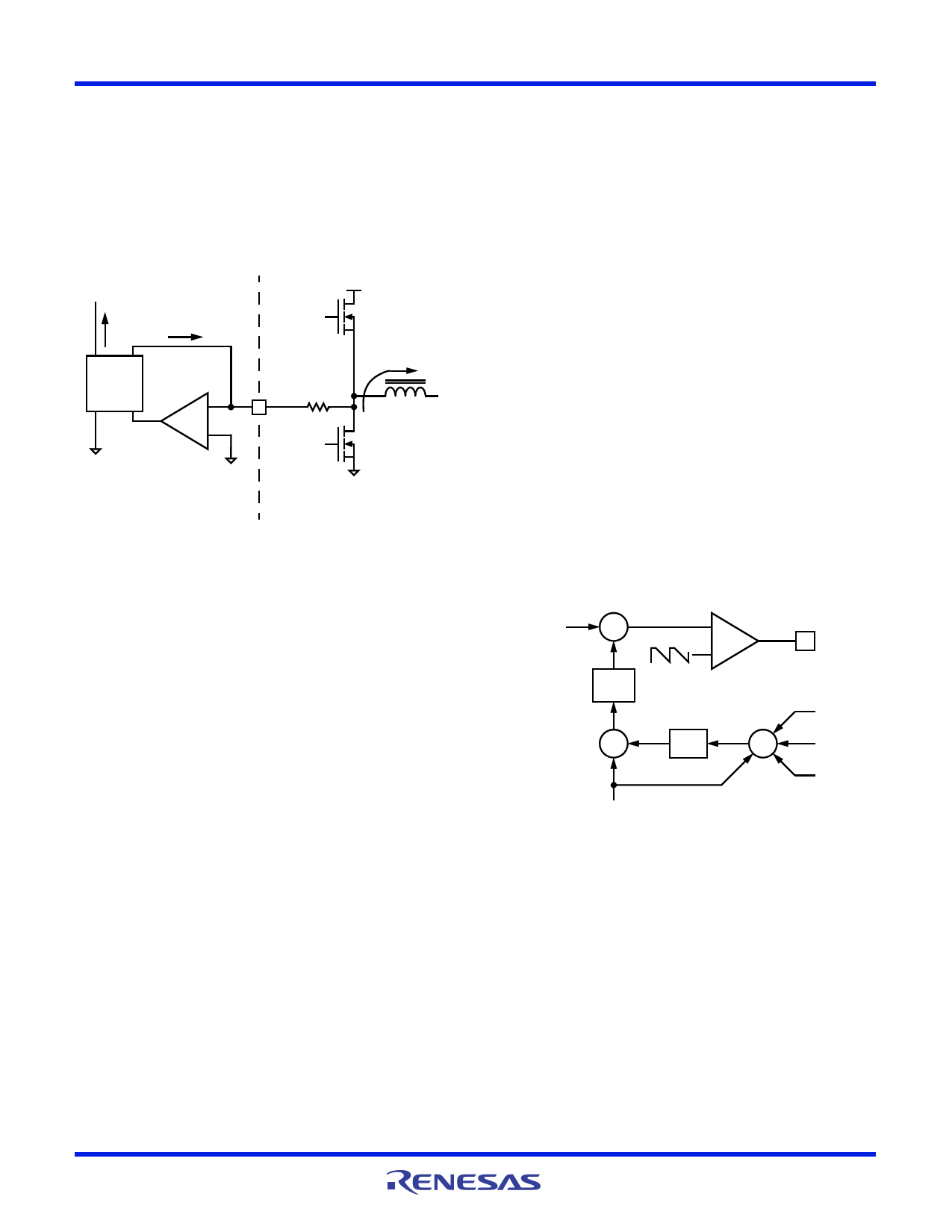
CURRENT SENSING
Intersil multi-phase controllers sense current by sampling the
voltage across the lower MOSFET during its conduction
interval. MOSFET rDS(ON) sensing is a no-added-cost method
to sense current for load-line regulation, channel-current
balance, module current sharing, and overcurrent protection. If
desired, an independent current-sense resistor in series with
the lower-MOSFET source can serve as a sense element in
place of the MOSFET rDS(ON).
VIN
In
ISEN = IL -r--D-R----SI--S-----EO----N-N-----
CHANNEL N
UPPER MOSFET
SAMPLE
&
HOLD
-
+
IL
ISEN(n)
RISEN
-
IL rDSON
+
CHANNEL N
LOWER MOSFET
ISL6557A INTERNAL CIRCUIT EXTERNAL CIRCUIT
FIGURE 4. INTERNAL AND EXTERNAL CURRENT-SENSING
CIRCUITRY
The ISEN input for each channel uses a ground-referenced
amplifier to reproduce a signal proportional to the channel
current (Figure 4). After sufficient settling time, the sensed
current is sampled, and the sample is used for current balance,
load-line regulation and overcurrent protection. The ISL6557A
samples channel current once each cycle. Figure 4 shows how
the sampled current, In, is created from the channel current IL.
The circuitry in Figure 4 represents the current measurement
and sampling circuitry for channel n in an N-channel converter.
This circuitry is repeated for each channel in the converter but
may not be active in channels 3 and 4 depending on the
particular implementation (see PWM Operation).
CHANNEL-CURRENT BALANCE
Another benefit of multi-phase operation is the thermal
advantage gained by distributing the dissipated heat over
multiple devices and greater area. By doing this, the designer
avoids the complexity of driving multiple parallel MOSFETs
and the expense of using expensive heat sinks and exotic
magnetic materials.
In order to fully realize the thermal advantage, it is important
that each channel in a multi-phase converter be controlled to
deliver about the same current at any load level. Intersil multi-
phase controllers guarantee current balance by comparing
each channel’s current to the average current delivered by all
channels and making an appropriate adjustment to each
channel’s pulse width based on the error. Intersil’s patented
current-balance method is illustrated in Figure 5 where the
average of the 2, 3, or 4 sampled channel currents combines
with the channel 1 sample, I1, to create an error signal IER.
FN9068 Rev 3.00
July 2004
The filtered error signal modifies the pulse width commanded
by VCOMP to correct any unbalance and force IER toward zero.
In some circumstances, it may be necessary to deliberately
design some channel-current unbalance into the system. In a
highly compact design, one or two channels may be able to
cool more effectively than the other(s) due to nearby air flow or
heat sinking components. The other channel(s) may have
more difficulty cooling with comparatively less air flow and heat
sinking. The hotter channels may also be located close to other
heat-generating components tending to drive their temperature
even higher. In these cases, a proper selection of the current
sense resistors (RISEN in Figure 4) introduces channel current
unbalance into the system. Increasing the value of RISEN in
the cooler channels and decreasing it in the hotter channels
moves all channels into thermal balance at the expense of
current balance.
OVERCURRENT PROTECTION
The average current, IAVG in Figure 5, is continually compared
with a constant 75A reference current. If the average current
at any time exceeds the reference current, the comparator
triggers the converter to shut down. All PWM signals are
placed in a high-impedance state which signals the drivers to
turn off both upper and lower MOSFETs. The system remains
in this state while the controller counts 2048 phase-clock
cycles.
VCOMP
+
-
f(j)
+
-
SAWTOOTH SIGNAL
IER
IAVG
-
N
+
PWM1
I4 *
I3 *
I2
I1
FIGURE 5. CHANNEL-1 PWM FUNCTION AND CURRENT-
BALANCE ADJUSTMENT
NOTE: *Channels 3 and 4 are optional.
This is followed by a soft-start attempt (see Soft-Start). If the
soft-start attempt is successful, operation will continue as
normal. Should the soft-start attempt fail, the ISL6557A
repeats the 2048-cycle wait period and follows with another
soft-start attempt. This hiccup mode of operation continues
Page 8 of 18
Share Link: 