HER301 데이터 시트보기 (PDF) - New Jersey Semiconductor
부품명
상세내역
일치하는 목록
HER301 Datasheet PDF : 2 Pages
| |||
J
*-s
20 STERN AVE.
SPRINGFIELD, NEW JERSEY 07081
U.S.A.
, One.
TELEPHONE: (973) 376-2922
(212)227-6005
FAX: (973) 376-8960
HER301 - HER308
PRV: 50-1000 Volts
lo : 3.0 Amperes
FEATURES:
* High current capability
* High surge current capability
* High reliability
* Low reverse current
* Low forward voltage drop
* Fast switching for high efficiency
* Pb / RoHS Free
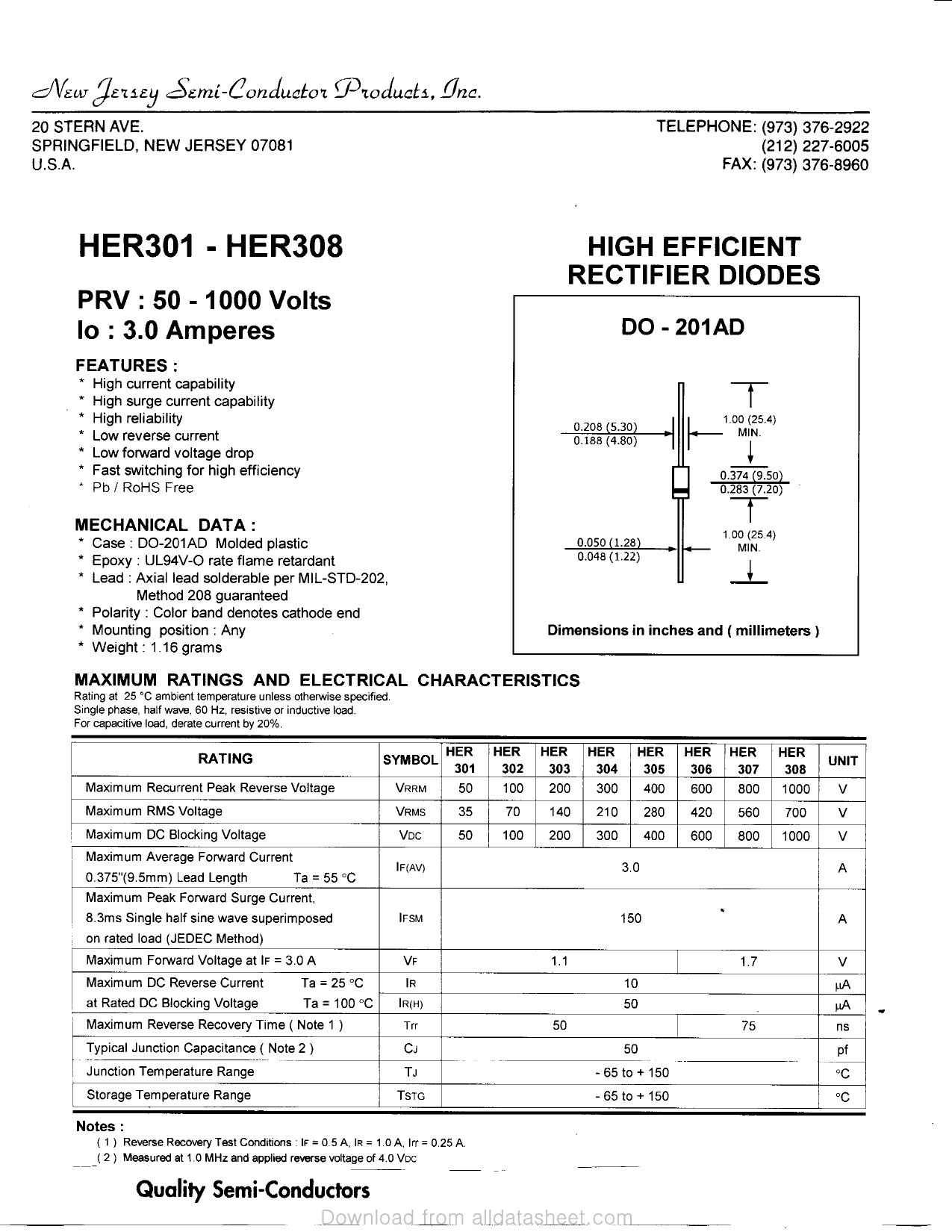
HIGH EFFICIENT
RECTIFIER DIODES
DO-201 AD
0.208 (5.30)
0.188 (4.80)
h-1.00(25.4)
MIN.
y
0.374 (9.50)
0.283 (7.20)
MECHANICAL DATA:
* Case : DO-201AD Molded plastic
* Epoxy : UL94V-O rate flame retardant
* Lead : Axial lead solderable per MIL-STD-202,
Method 208 guaranteed
* Polarity : Color band denotes cathode end
* Mounting position : Any
* Weight: 1.16 grams
0.050(1.28)
0.048(1.22)
1.00(25.4)
MIN.
Dimensions in inches and ( millimeters )
MAXIMUM RATINGS AND ELECTRICAL CHARACTERISTICS
Rating at 25 °C ambient temperature unless otherwise specified.
Single phase, half wave, 60 Hz, resistive or inductive load.
For capacitive load, derate current by 20%.
RATING
Maximum Recurrent Peak Reverse Voltage
SYMBOL HER
301
VRRM
50
Maximum RMS Voltage
VRMS
35
Maximum DC Blocking Voltage
VDC
50
Maximum Average Forward Current
0.375"(9.5mm) Lead Length
Ta = 55 °C
Maximum Peak Forward Surge Current,
8.3ms Single half sine wave superimposed
on rated load (JEDEC Method)
Maximum Forward Voltage at IF = 3.0 A
lF(AV)
IFSM
VF
Maximum DC Reverse Current
Ta = 25 °C
|R
at Rated DC Blocking Voltage
Ta = 100 °C |R(H)
Maximum Reverse Recovery Time ( Note 1 )
Trr
Typical Junction Capacitance ( Note 2 )
CJ
Junction Temperature Range
TJ
Storage Temperature Range
TSTG
HER
302
100
70
100
HER
303
200
140
200
1.1
50
HER
304
300
210
300
HER
305
400
280
400
HER
306
600
420
600
HER
307
800
560
800
30
«
1!50
1.7
10
50
75
50
- 6 5 t c) + 150
- 6 5 t c) + 150
HER
308
1000
700
1000
UNIT
V
V
V
A
A
V
MA
uA
ns
Pf
°f*
°C
Notes :
( 1 ) Reverse Recovery Test Conditions : IF = 0.5 A, IR = 1.0 A, Irr = 0.25 A.
( 2 ) Measured at 1.0 MHz and applied reverse voltage of 4.0 VDC
Quality Semi-Conductors
Share Link: 