NCP1547(2007) 데이터 시트보기 (PDF) - ON Semiconductor
부품명
상세내역
일치하는 목록
NCP1547 Datasheet PDF : 13 Pages
| |||
NCP1547
COMPONENT SELECTION
Input Capacitor
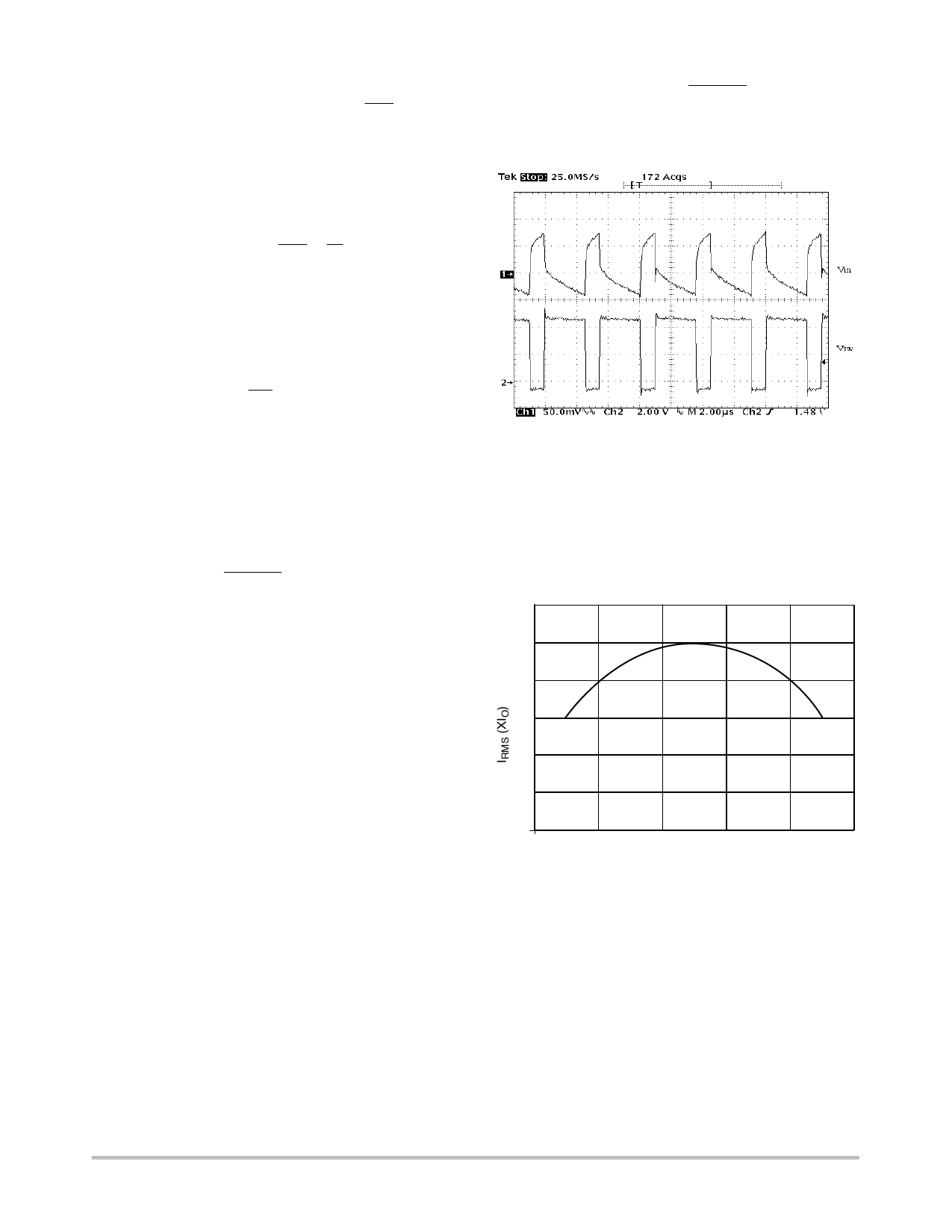
In a buck converter, the input capacitor witnesses pulsed
current with an amplitude equal to the load current. This
pulsed current and the ESR of the input capacitors determine
the VIN ripple voltage, which is shown in Figure 10. For VIN
ripple, low ESR is a critical requirement for the input
capacitor selection. The pulsed input current possesses a
significant AC component, which is absorbed by the input
capacitors. The RMS current of the input capacitor can be
calculated using:
IRMS + IO ǸD(1 * D)
where:
D = switching duty cycle which is equal to VO/VIN.
IO = load current.
Figure 10. Input Voltage Ripple in a Buck Converter
To calculate the RMS current, multiply the load current
with the constant given by Figure 11 at each duty cycle. It is
a common practice to select the input capacitor with an RMS
current rating more than half the maximum load current. If
multiple capacitors are paralleled, the RMS current for each
capacitor should be the total current divided by the number
of capacitors.
0.6
0.5
0.4
0.3
0.2
0.1
00
0.2
0.4
0.6
0.8
1.0
DUTY CYCLE
Figure 11. Input Capacitor RMS Current can be
Calculated by Multiplying Y Value with Maximum Load
Current at any Duty Cycle
Selecting the capacitor type is determined by each
design’s constraint and emphasis. The aluminum
electrolytic capacitors are widely available at lowest cost.
Their ESR and ESL (equivalent series inductor) are
relatively high. Multiple capacitors are usually paralleled to
achieve lower ESR. In addition, electrolytic capacitors
usually need to be paralleled with a ceramic capacitor for
filtering high frequency noises. The OS−CON are solid
aluminum electrolytic capacitors, and therefore has a much
lower ESR. Recently, the price of the OS−CON capacitors
has dropped significantly so that it is now feasible to use
them for some low cost designs. Electrolytic capacitors are
physically large, and not used in applications where the size,
and especially height is the major concern.
Ceramic capacitors are now available in values over 10 mF.
Since the ceramic capacitor has low ESR and ESL, a single
ceramic capacitor can be adequate for both low frequency
and high frequency noises. The disadvantage of ceramic
capacitors are their high cost. Solid tantalum capacitors can
have low ESR and small size. However, the reliability of the
tantalum capacitor is always a concern in the application
where the capacitor may experience surge current.
Output Capacitor
In a buck converter, the requirements on the output
capacitor are not as critical as those on the input capacitor.
The current to the output capacitor comes from the inductor
and thus is triangular. In most applications, this makes the
RMS ripple current not an issue in selecting output
capacitors.
The output ripple voltage is the sum of a triangular wave
caused by ripple current flowing through ESR, and a square
wave due to ESL. Capacitive reactance is assumed to be
small compared to ESR and ESL. The peak to peak ripple
current of the inductor is:
IP
*
P
+
VO(VIN * VO)
(VIN)(L)(fS)
VRIPPLE(ESR), the output ripple due to the ESR, is equal
to the product of IP−P and ESR. The voltage developed
across the ESL is proportional to the di/dt of the output
capacitor. It is realized that the di/dt of the output capacitor
is the same as the di/dt of the inductor current. Therefore,
when the switch turns on, the di/dt is equal to (VIN − VO)/L,
and it becomes VO/L when the switch turns off. The total
ripple voltage induced by ESL can then be derived from
VRIPPLE(ESL)
+
VO
ESL( L )
)
ESL(VIN
*
L
VO)
+
ESL(VLIN)
The total output ripple is the sum of the VRIPPLE(ESR) and
VRIPPLE(ESL).
http://onsemi.com
10
Share Link: 