CS8161 데이터 시트보기 (PDF) - Cherry semiconductor
부품명
상세내역
일치하는 목록
CS8161 Datasheet PDF : 8 Pages
| |||
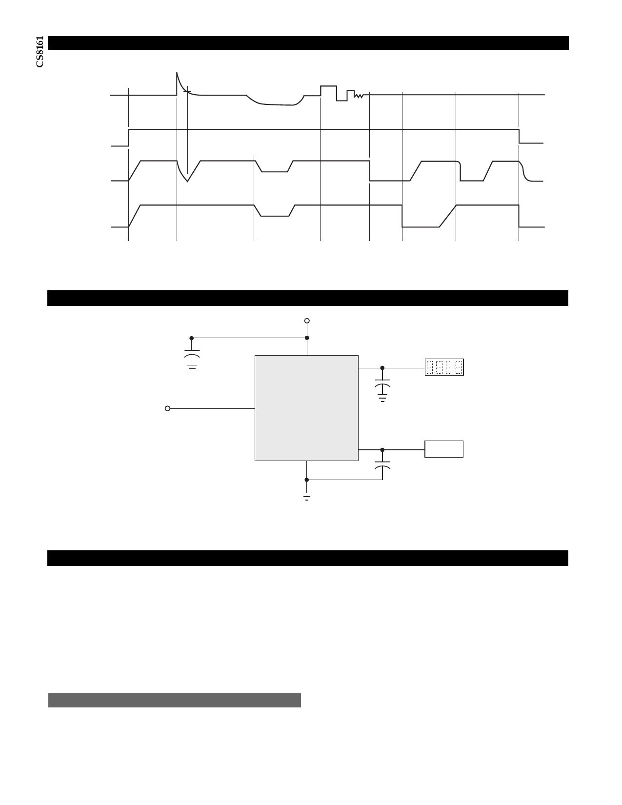
Typical Circuit Waveform
60V
VIN 14V
31V
26V
3V
14V
ENABLE 2.0V
0.8V
VOUT1 0V
VOUT2 0V
12V
5V
System
Condition
Turn
On
Load
Dump
12V
12V
2.4V
5V
2.4V
12V
0V
0V
5V
0V
Low VIN
Line Noise, Etc.
VOUT1
Short
Circuit
VOUT2
Short
Circuit
Application Diagram
Thermal
Shutdown
VOUT1
12V
0V
0V
Turn
Off
C1*
0.1 mF
VIN
VOUT1
+
C2**
CS8161
22mF
ENABLE
Display
Gnd
VOUT2
+
C3**
22mF
Tuner
NOTES:
* C1 required if regulator is located far from power supply filter.
** C2, C3 required for stability, value may be increased. Capacitor must operate at minimum temperature expected.
Application Notes
Since both outputs are controlled by the same ENABLE,
the CS8161 is ideal for applications where a sleep mode is
required. Using the CS8161, a section of circuitry such as a
display and nonessential 5V circuits can be shut down
under microprocessor control to conserve energy.
The example in the Applications Diagram shows an auto-
motive radio application where the display is powered by
the 12V on VOUT1 and the Tuner IC is powered by the 5V
on VOUT2. Neither output is required unless both the igni-
tion and the Radio On/Off switch are on.
Stability Considerations
The output compensation capacitor (Application diagram
C2 and C3) helps determine three main characteristics of a
linear regulator: start-up delay, load transient response
and loop stability.
The capacitor value and type should be based on cost,
availability, size and temperature constraints. A tantalum
or aluminum electrolytic capacitor is best, since a film or
ceramic capacitor with almost zero ESR, can cause insta-
bility. The aluminum electrolytic capacitor is the least
expensive solution, but, if the circuit operates at low tem-
peratures (-25¡C to -40¡C), both the value and ESR of the
capacitor will vary considerably. The capacitor manufac-
turers data sheet usually provide this information.
The values for the output capacitors C2 and C3 shown in
the Applications Circuit should work for most applica-
tions, however it is not necessarily the best solution.
To determine an acceptable value for C2 and C3 for a par-
ticular application, start with tantalum capacitors of the
recommended value on each output and work towards
less expensive alternative parts for each output in turn.
6
Share Link: 