MC10136 데이터 시트보기 (PDF) - Motorola => Freescale
부품명
상세내역
일치하는 목록
MC10136 Datasheet PDF : 8 Pages
| |||
MC10136
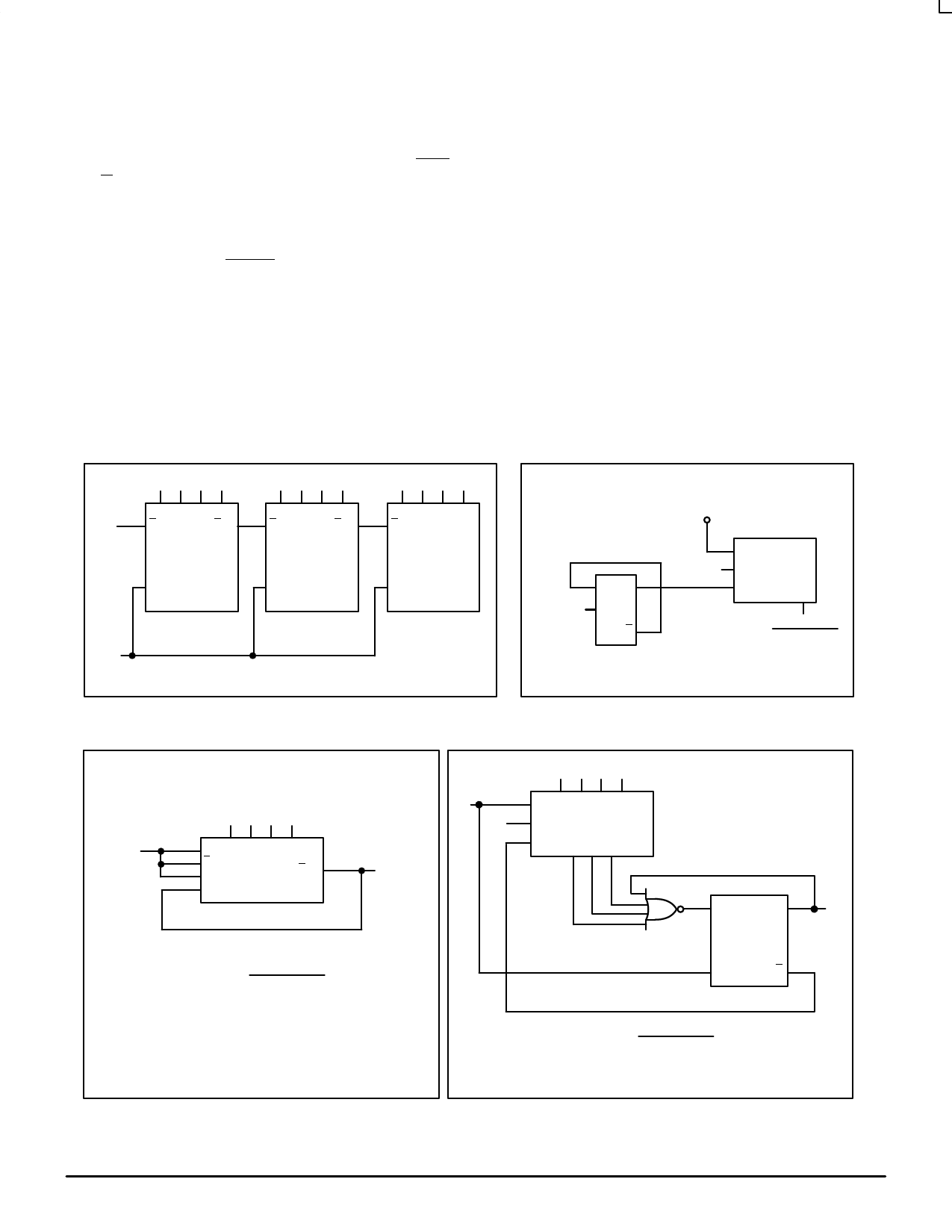
APPLICATIONS INFORMATION
To provide more than four bits of counting capability
The MC10136 may also be used as a programmable
several MC10136 counters may be cascaded. The Carry
counter. The configuration of Figure 3 requires no
In input overrides the clock when the counter is either in
the increment mode or the decrement mode of operation.
This input allows several devices to be cascaded in a fully
synchronous multistage counter as illustrated in Figure 1.
The carry is advanced between stages as shown with no
external gating. The Carry In of the first device may be left
open. The system clock is common to all devices.
The various operational modes of the counter make it
useful for a wide variety of applications. If used with MECL
III devices, prescalers with input toggle frequencies in
excess of 300 MHz are possible. Figure 2 shows such a
prescaler using the MC10136 and MC1670. Use of the
MC10231 in place of the MC1670 permits 200 MHz
operation.
additional gates, although maximum frequency is limited
to about 50 MHz. The divider modulus is equal to the
program input plus one (M = N + 1), therefore, the counter
will divide by a modulus varying from 1 to 16.
A second programmable configuration is also illustrated
in Figure 4. A pulse swallowing technique is used to speed
the counter operation up to 110 MHz typically. The divider
modulus for this figure is equal to the program input (M =
N). The minimum modulus is 2 because of the pulse
swallowing technique, and the modulus may vary from 2
to 15. This programmable configuration requires an
additional gate, such as 1/2MC10109 and a flip-flop such
as 1/2MC10131.
FIGURE 1 — 12 BIT SYNCHRONOUS COUNTER
FIGURE 2 — 300 MHz PRESCALER
LSB
Q0 Q1 Q2 Q3
Cin
Cout
Q0 Q1 Q2 Q3
Cin
Cout
MSB
Q0 Q1 Q2 Q3
Cin
C
C
C
System
Clock
NOTE: S1 and S2 are set either for increment or decrement operation.
Input
Frequency
DQ
C
Q
MC1670
Logic High
MC10136
S1
S2
C
Q3
Input Frequency
32
FIGURE 3 — 50 MHz PROGRAMMABLE COUNTER
Program Input
fin
C D0 D1 D2 D3
Cin
S2
Cout
fout
S1
1
fout
=
fin
Program Input + 1
2 fmax ≅ 50 MHz Typ.
3 Divide Ratio is from 1 to 16.
FIGURE 4 — 100 MHz PROGRAMMABLE COUNTER
Program Input
fin
C D0 D1 D2 D3
S2
MC10136
S1 Q0 Q2 Q3
D
Q
fout
1/2MC10109
1/2MC10131
C
Q
1 fout =
fin
Program Input
2 fmax ≅ 110 MHz Typ.
3 Divide Ratio is from 2 to 15.
MOTOROLA
3–32
MECL Data
DL122 — Rev 6
Share Link: 