EGP20A 데이터 시트보기 (PDF) - SUNMATE electronic Co., LTD
부품명
상세내역
일치하는 목록
EGP20A Datasheet PDF : 2 Pages
| |||
EGP20A-EGP20M
2.0A Axial Leaded High Efficiency Rectifier
Features
· GPRC (Glass Passivated Rectifier Chip) inside
· Glass passivated cavity-free junction
· Superfast recovery time for high efficiency
· Low forward voltage , high current capability
· Low leakage current
· High surge current capability
· High temperature soldering guaranteed: 260oC/10 seconds,
0.375" (9.5mm) lead length, 5lbs. (2.3 kg) tension
· Plastic package has Underwriters Laboratory Flammability
Classification 94V-0
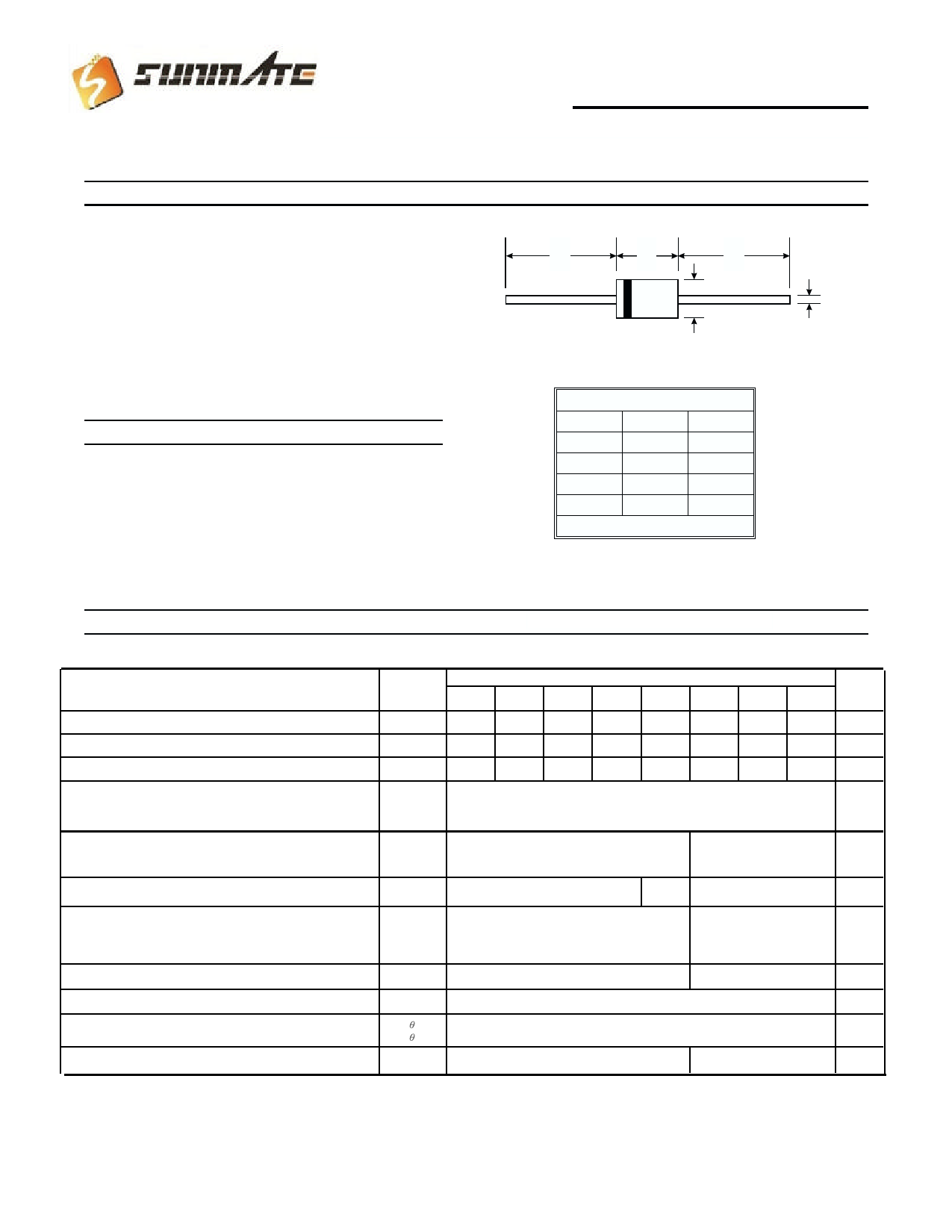
Mechanical Data
· Case : JEDEC DO- 15 molded plastic over glass body
· Terminals : Plated axial leads , solderable per MIL-STD-750,
Method 2026
· Polarity : Color band denotes cathode end
· Mounting Position : Any
· Weight : 0.015 ounes , 0.4 gram
A
B
A
C
D
DO-15
Dim
Min
Max
A
25.40
¾
B
5.50
7.62
C
0.686
0.889
D
2.60
3.60
All Dimensions in mm
Maximum Ratings and Electrical Characteristics @ TA = 25°C unless otherwise specified
Ratings at 25 oC ambient temperature
unless otherwise specified.
Maximum repetitive peak reverse voltage
Maximum RMS voltage
Maximum DC blocking voltage
SYMBOLS
A
VRRM
50
VRMS
35
VDC
50
EGP20
B
D
F
G
100
200
300
400
70
140
210
280
100
200
300
400
Maximum average forward rectified current
I (AV)
2.0
0.375" (9.5mm) lead length (SEE FIG.1)
Peak forward surge current 8.3ms single half sine-wave
IFSM
65
superimposed on rated load (JEDEC Method)
Maximum instantaneous forward voltage at 2.0 A
VF
Maximum DC reverse current
at rated DC blocking voltage
TA=25oC
TA=125oC
IR
TA=150oC
Maximum reverse recovery time (NOTE 1)
trr
1.0
1.25
5
30
100
50
Typical junction capacitance (NOTE 2)
Typical thermal resistance (NOTE 3)
Operating junction and storage temperature range
CJ
R JA
R JL
TJ,TSTG
45
40
15
-65 to +175
NOTES : (1) Reverse recovery test condition : IF 0.5A, IR=1.0A, Irr=0.25A
(2) Measured at 1.0 MHz and applied reverse voltage of 4.0 Volts
(3) Thermal resistance from junction to ambient at 0.375" (9.5mm) lead lengths, P.C.B. mounted.
UNITS
J
K
M
600
800 1000 Volts
420
560
700 Volts
600
800 1000 Volts
Amps
60
1.7
5
100
-
75
-55 to +150
Amps
Volts
uA
nS
pF
oC / W
oC
1 of 2
Share Link: 