M95320-MB3TP 데이터 시트보기 (PDF) - STMicroelectronics
부품명
상세내역
일치하는 목록
M95320-MB3TP Datasheet PDF : 42 Pages
| |||
M95640, M95320
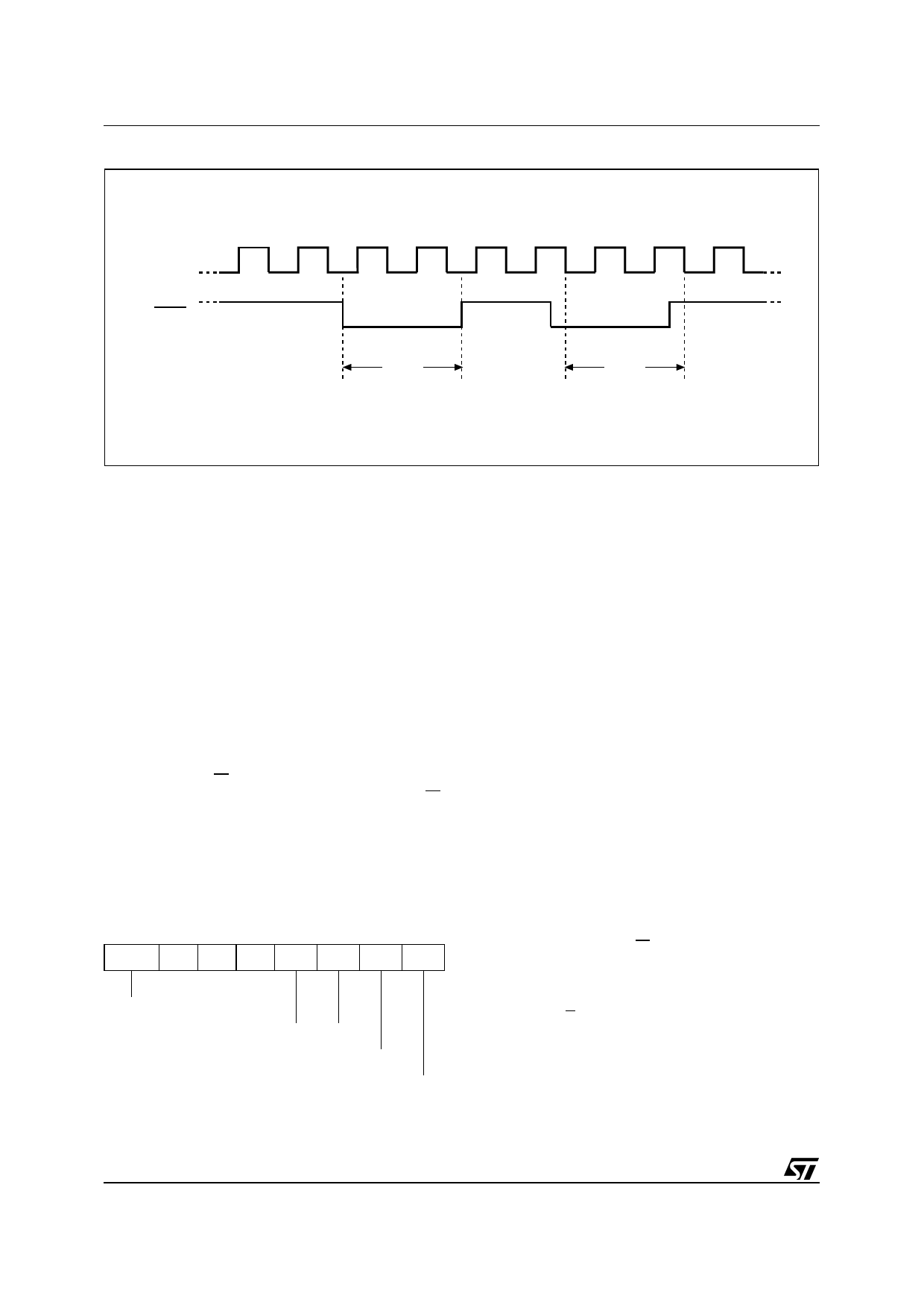
Figure 6. Hold Condition Activation
C
HOLD
Hold
Condition
Hold
Condition
AI02029D
Status Register
Figure 7. shows the position of the Status Register
in the control logic of the device. The Status Reg-
ister contains a number of status and control bits
that can be read or set (as appropriate) by specific
instructions.
WIP bit. The Write In Progress (WIP) bit indicates
whether the memory is busy with a Write or Write
Status Register cycle.
WEL bit. The Write Enable Latch (WEL) bit indi-
cates the status of the internal Write Enable Latch.
BP1, BP0 bits. The Block Protect (BP1, BP0) bits
are non-volatile. They define the size of the area to
be software protected against Write instructions.
SRWD bit. The Status Register Write Disable
(SRWD) bit is operated in conjunction with the
Write Protect (W) signal. The Status Register
Write Disable (SRWD) bit and Write Protect (W)
signal allow the device to be put in the Hardware
Protected mode. In this mode, the non-volatile bits
of the Status Register (SRWD, BP1, BP0) become
read-only bits.
Table 4. Status Register Format
b7
b0
SRWD 0 0 0 BP1 BP0 WEL WIP
Status Register Write Protect
Block Protect Bits
Write Enable Latch Bit
Write In Progress Bit
Data Protection and Protocol Control
Non-volatile memory devices can be used in envi-
ronments that are particularly noisy, and within ap-
plications that could experience problems if
memory bytes are corrupted. Consequently, the
device features the following data protection
mechanisms:
■ Write and Write Status Register instructions
are checked that they consist of a number of
clock pulses that is a multiple of eight, before
they are accepted for execution.
■ All instructions that modify data must be
preceded by a Write Enable (WREN)
instruction to set the Write Enable Latch
(WEL) bit. This bit is returned to its reset state
by the following events:
– Power-up
– Write Disable (WRDI) instruction
completion
– Write Status Register (WRSR) instruction
completion
– Write (WRITE) instruction completion
■ The Block Protect (BP1, BP0) bits allow part of
the memory to be configured as read-only.
This is the Software Protected Mode (SPM).
■ The Write Protect (W) signal allows the Block
Protect (BP1, BP0) bits to be protected. This is
the Hardware Protected Mode (HPM).
For any instruction to be accepted, and executed,
Chip Select (S) must be driven High after the rising
edge of Serial Clock (C) for the last bit of the in-
struction, and before the next rising edge of Serial
Clock (C).
Two points need to be noted in the previous sen-
tence:
10/42
Share Link: 