HRDR610B5 데이터 시트보기 (PDF) - ABB
부품명
상세내역
일치하는 목록
HRDR610B5 Datasheet PDF : 2 Pages
| |||
Recycling (Pulse Generator)
HRDR Power-Time
Time Delay Relay
30 A SPDT N.O. Output
Contacts
12 ... 230 V Operation in
5 Ranges
Encapsulated Circuitry
Delays from 100 ms ...
1000 m in 6 Ranges
Independent Adjustment of
ON and OFF Delays
+/-0.5% Repeat Accuracy
+/-5% Factory Calibration
Fixed or Onboard or External
Adjustment
Approvals:
Description
The HRDR Series combines an electromechanical relay and microcontroller timing circuitry. It offers 12 to
230 V operation in five ranges and factory fixed, onboard or externally adjustable time delays with a repeat
accuracy of +/-0.5%. The high switching capacity of the output contacts allow for direct control of heavy loads
like compressors, pumps, motors, heaters, and lighting. Bypass/reset switch option allows operator to
interrupt normal recycling sequence and energize output relay. An excellent choice for OEM applications.
Operation
Upon application of input voltage, the ON time T1
begins and output relay energizes. At the end of the
ON time, the output relay de-energizes and the OFF
time T2 begins. At the end of the OFF time, the output
relay energizes and the cycle repeats as long as input
voltage is applied. Some recycling timers have the
OFF time as the first delay.
Reset: Removing input voltage resets output and
time delays, and returns sequence to the first delay.
Bypass/Reset Switch: Closing the normally open
bypass/reset switch energizes the output relay and
resets the time delays. Opening the switch restarts
recycling operation with the first delay.
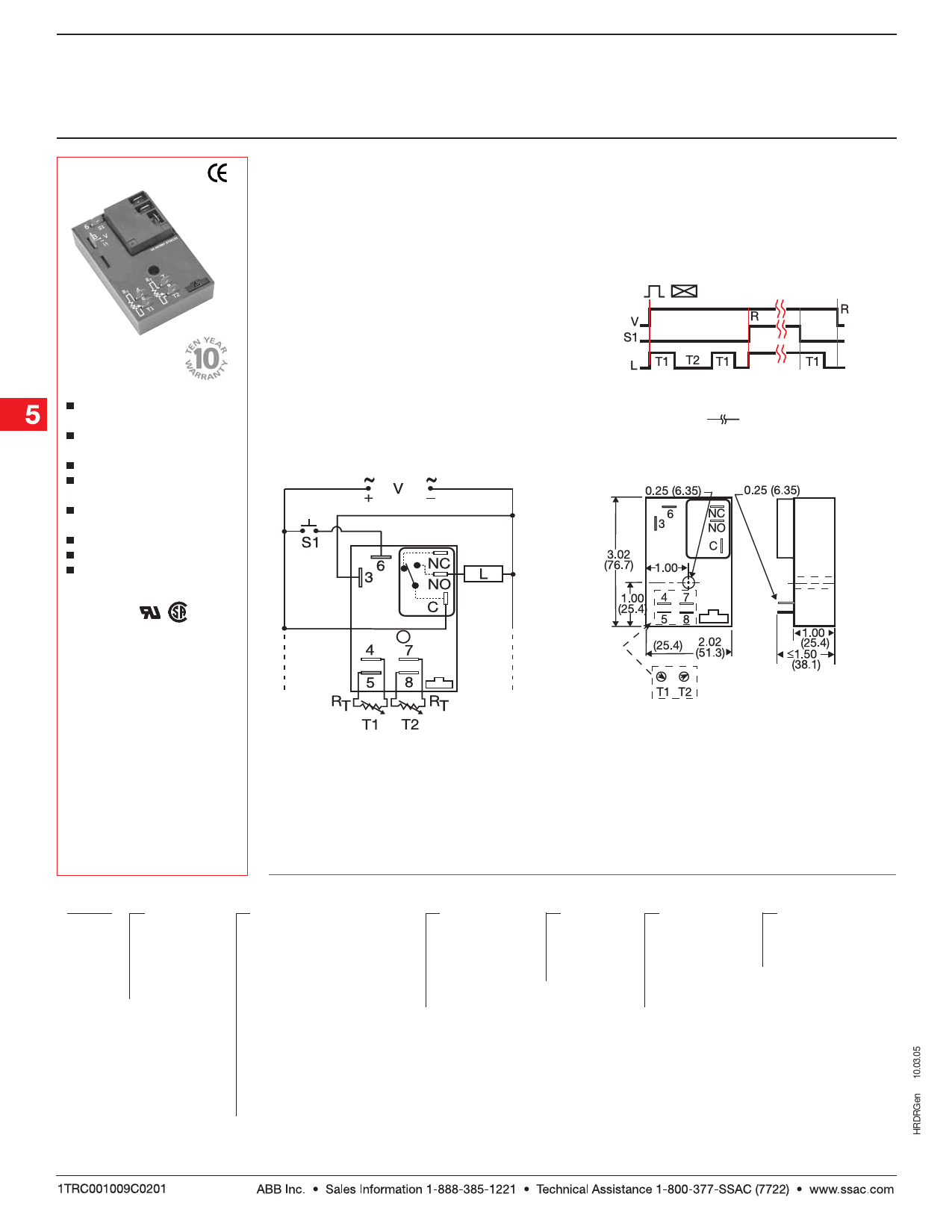
Function
Recycling w/Reset Switch
V = Voltage S1 = Reset Switch
L = Load R = Reset T1 = ON Time
T2 = OFF Time
= Undefined time
Connection
Mechanical View
Note: Terminals 4 & 5 and/or 7 & 8 are only
included on externally adjustable units.
NO = Normally Open S1 = Reset Switch
C = Common, Transfer Contact L = Load
Relay contacts are non-isolated. RT is included
when external adjustment is ordered. Dashed
lines are internal connections. Terminal 6 is
included when Bypass/Reset is selected.
Inches (Millimeters)
Ordering Table
HRDR X
Series
Input
– 1 - 12 V DC
– 2 - 24 V AC
– 3 - 24 V DC
– 4 - 120 V AC
– 6 - 230 V AC
Example P/N:
HRDR431A4R
Fixed – HRDR410.2SB100S
X
External Adjust
– 1 - Both Times Fixed
– 2 - Both Times Onboard Adj.
– 3 - Both Times External Adj.
– 4 - ON Time External Adj.
OFF Time Fixed
– 5 - ON Time Fixed
OFF Time External Adj.
– 6 - ON Time Onboard Adj.
OFF Time, Fixed
– 7 - ON Time, Fixed
OFF Time Onboard Adj.
– 8 - ON Time Onboard Adj.
OFF Time, External Adj.
– 9 - ON Time, External Adj.
OFF Time Onboard Adj.
X
T1 ON Time *
– 0 - 0.1 ... 10 s
– 1 - 1 ... 100 s
– 2 - 10 ... 1000 s
– 3 - 0.1 ... 10 m
– 4 - 1 ... 100 m
– 5 - 10... 1000 m
X
Operating
Sequence
– A - ON Time
First
– B - OFF Time
First
X
T2 OFF Time *
– 0 - 0.1 ... 10 s
– 1 - 1 ... 100 s
– 2 - 10 ... 1000 s
– 3 - 0.1 ... 10 m
– 4 - 1 ... 100 m
– 5 - 10 ...1000 m
X
Operation
Blank - No Bypass/
Reset Option
– R - Bypass/Reset
Option
* If Fixed Delay is selected, insert
delay [ 0.1 … 1000 ] followed by ( S )
sec. or [ 0.1 ... 1000 ] ( M ) min.
5.168
Low Voltage Products & Systems
Share Link: 