LLL317R71H103MD01K 데이터 시트보기 (PDF) - Unspecified
부품명
상세내역
일치하는 목록
LLL317R71H103MD01K Datasheet PDF : 296 Pages
| |||
!Note • Please read rating and !CAUTION (for storage, operating, rating, soldering, mounting and handling) in this catalog to prevent smoking and/or burning, etc.
• This catalog has only typical specifications. Therefore, please approve our product specifications or transact the approval sheet for product specifications before ordering.
Explanation of Symbols in This Catalog
WEB
Links are provided to the latest information from the PDF version of the catalog, which is available on the web.
C02E.pdf
Nov.27,2017
For applications that do not require the particular reliability such as
the general equipment
Infotainment for Automotive
The product for entertainment equipment like car navigations, car
audios, and body control equipment like wipers, power windows.
Powertrain/Safety for Automotive
Product used for applications (running, turning, stopping and safety
devices) which particularly concern human life, such as in devices for
automobiles.
Medical-grade products for Implanted Medical Devices
These products are intended for use in implanted medical devices
such as cardiac pacemakers, cochlear implants, insulin pumps and
gastric electrostimulators.
They are suitable for use in non-critical circuits. *1
*1 Non-critical circuits
This term refers to circuits in implanted medical devices that are
not directly linked to life support, i.e. circuits that will not directly
endanger the life of the patient should the functionality of the
device be reduced or halted by failure of the circuit.
AEC-Q200 compliant product
Safety Standard Certified Product
Products that acquired safety standard certification IEC60384-14
and products based on the Electrical Appliance and Material Safety
Law of Japan.
Based on the Electrical Appliance and Material Safety Law of Japan
Products that are based on the electrical appliance and material
safety law of Japan.
Low dissipation for high frequency
By devising ceramic materials and electrode materials, low
dissipation is achieved in frequency bands of VHF, UHF and
microwave or beyond.
Low inductance
This capacitor is designed so that the parasitic inductance
component (ESL) that the capacitor has on the high frequency side
becomes lower.
Fail safe product
This capacitor is designed to prevent failures as much as possible by
short mode.
Product resistant to deflection cracking
This capacitor is designed to prevent failures as much as possible by
short mode caused by cracking when there is board deflection.
Product with solder cracking suppression
“This capacitor is configured with metal terminals and leads
connected to the chip. The metal terminals and leads relieve the
stress from expansion and contraction of the solder, to suppress
solder cracking.”
Product suitable for acoustic noise reduction and low distortion
This product suppresses acoustic noise, which occurs when a
ceramic capacitor is used, by devising the materials and
configuration.
No DC bias characteristics
Polymer capacitor is no capacitance change with DC bias due to
aluminum oxidized film for dielectric.
Low-inductance product suitable for noise suppression.
This product has extremely low ESL and is suitable for suppression
of noise, including high frequencies.
This product can also be used as a low-ESL, high-performance
bypass capacitor.
Product for bonding
Since gold is used for the external electrodes, the capacitor can be
mounted by die bonding/wire bonding.
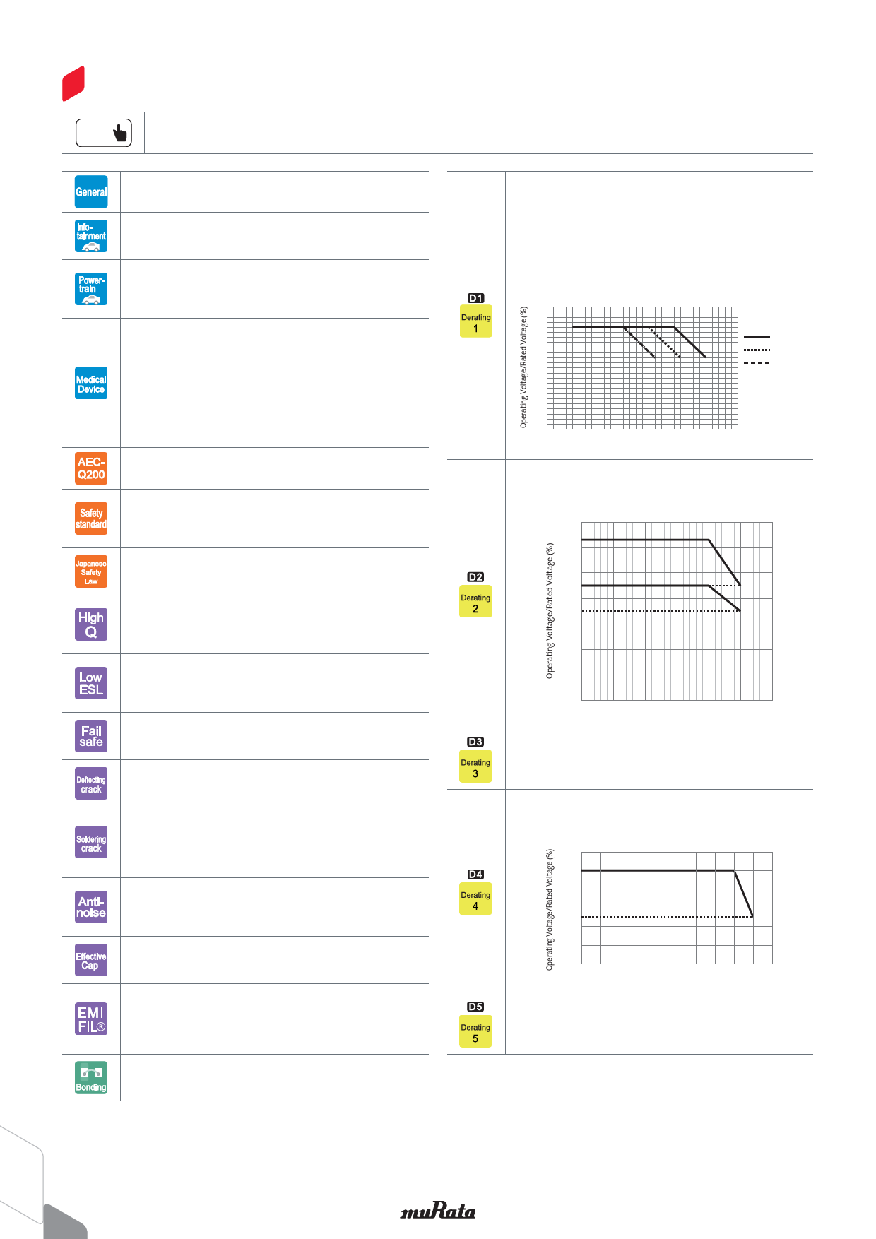
Derating 1
This product is suitable when a voltage continuously applied to a
capacitor in an operating circuit, is used below (derated) the rated
voltage of the capacitor. This model guarantees the test conditions in
the endurance test, at a rated voltage x 100% at the maximum
operating temperature. A reliability assurance level equivalent to a
common product can be secured, by using this product within the
voltage and temperature derated conditions recommended in the
figure below.
Recommended Conditions of the Derating Operating Voltage and Temperature
120
100
125°C Type
80
105°C Type
85°C Type
60
40
20
0
0
25
50
75
100 125 150
Product Temperature (°C)
Derating 2
When the product temperature exceeds 105°C, please use this
product within the voltage and temperature derated conditions in the
figure below.
700
Rated Voltage 630V
600
500
(450V)
400
(350V)
300
Rated Voltage 450V
200
100
0
0
25
50
75
100 125 150
Product Temperature (°C)
Derating 3
Please apply the derating curve according to the operating
temperature.
Please refer to detailed specifications sheet for details.
Derating 4
When the product temperature exceeds 125°C, please use this
product within the voltage and temperature derated conditions in the
figure below.
120
100
80
60
(50)
40
20
0
-75 -50 -25 0 25 50 75 100 125 150 175
Product Temperature (°C)
Derating 5
Please apply the rated voltage derating over 150 °C.
Please refer to detailed specifications sheet for details.
2
Share Link: 