SCY99079BDR2G 데이터 시트보기 (PDF) - ON Semiconductor
부품명
상세내역
일치하는 목록
SCY99079BDR2G Datasheet PDF : 28 Pages
| |||
DAP018A/B/C/D/F
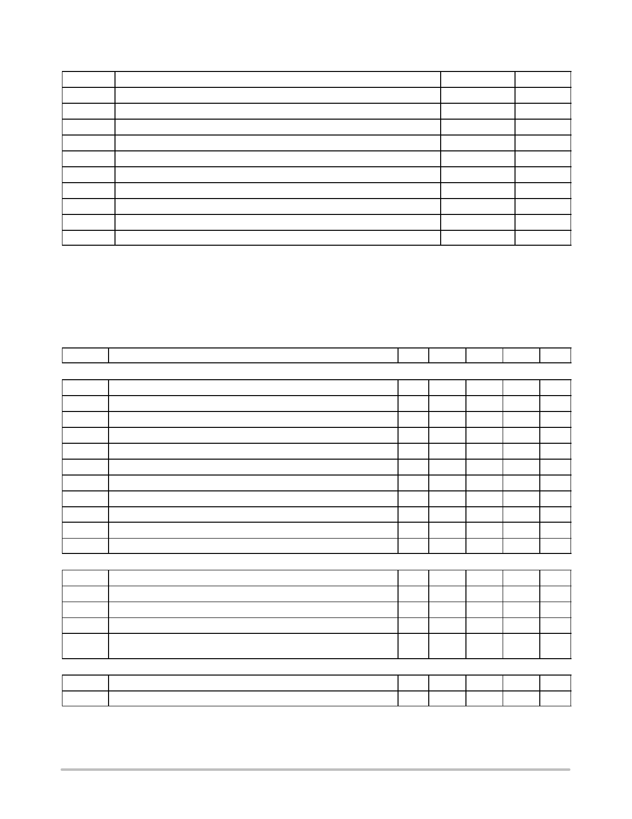
MAXIMUM RATINGS TABLE
Symbol
Rating
Value
Unit
VCCmax
ICCmax
Maximum Power Supply Voltage, VCC Pin, Continuous Voltage
Maximum Current for VCC Pin
Maximum Voltage on Low Power Pins (Except Pins 9, 10 and 14)
−0.3 to 28
V
$30
mA
−0.3 to 10
V
IOPP Maximum Injected Negative Current into the OPP Pin (Pin 1)
−2
mA
RθJ−A
TJMAX
Thermal Resistance Junction−to−Air
Maximum Junction Temperature
Storage Temperature Range
120
150
−60 to +150
°C/W
°C
°C
ESD Capability, Human Body Model (All pins except HV)
2
kV
ESD Capability, Machine Model
180
V
Maximum Voltage on Pin 14 (HV)
−0.3 to 500
V
Stresses exceeding Maximum Ratings may damage the device. Maximum Ratings are stress ratings only. Functional operation above the
Recommended Operating Conditions is not implied. Extended exposure to stresses above the Recommended Operating Conditions may affect
device reliability.
NOTES:This device(s) contains ESD protection and exceeds the following tests:
Human Body Model 2000V per JEDEC Standard JESD22−A114E
Machine Model 200V per JEDEC Standard JESD22−A115−A
This device contains latch−up protection and exceeds 100 mA per JEDEC Standard JESD78 except pin 12.
ELECTRICAL CHARACTERISTICS
(For typical values TJ = 25°C, for min/max values TJ = −25°C to +125°C, Max TJ = 150°C, VCC = 12 V unless otherwise noted)
Symbol
Rating
Pin Min
Typ
Max Unit
SUPPLY SECTION
VCCON VCC increasing level at which the current source turns−off
VCC(min) VCC level below which output pulses are stopped
VCClatch VCC decreasing level at which the latch−off phase ends
VCCreset Internal latch reset level
resetHyst Minimum voltage difference between VCClatch and VCCreset, TJ > 0°C
VCCTSD VCC voltage when the TSD is activated (Note 2)
ICC1 Internal IC consumption, no output load on pin 9
ICC1light ICC1 for a feedback voltage equal to Vfold (internal bias reduction)
ICC2 Internal IC consumption, 1 nF output load on pin 9
ICC3 Internal IC consumption, latch−off phase
ITSD Current consumption in TSD mode
INTERNAL START−UP CURRENT SOURCE – High−voltage pin biased to 60 Vdc.
10
14
15
16
V
10
8
9
10
V
10
7.2
7.5
8.0
V
10
5
V
−
0.8
V
−
6.5
7.1
V
10
1.9
mA
10
1.5
mA
10
2.7
mA
10
0.6
mA
−
400
mA
Symbol
Rating
Pin Min
Typ
Max Unit
IC2
High−voltage current source, VCC = 10 V
IC1
High−voltage current source, VCC = 0, TJ = 25°C
VTh
VCC transition level for IC1 to IC2 toggling point
Ileak
Leakage current for the high voltage source,
Vpin 14 = 500 Vdc, VCC = 12 V, TJ > 0°C
14
3
6
9
mA
14
150
650 1200 mA
14
0.9
V
14
1
15
30
mA
DRIVE OUTPUT
Symbol
Rating
Pin Min
Typ
Max Unit
Tr
Output voltage rise−time @ CL = 1 nF, 10−90% of a 12 V output signal
9
−
40
−
ns
1. See characterization table for linearity over negative bias voltage.
2. Guaranteed by design.
3. The OTP parameters are selected to cope with a TTC03−474 which offers a resistance of 8.8 kW when heated to a temperature of 110°C.
4. The brown−out circuitry is disabled on versions A & C and operates on versions B & D.
http://onsemi.com
5
Share Link: 