SCY99079BDR2G 데이터 시트보기 (PDF) - ON Semiconductor
부품명
상세내역
일치하는 목록
SCY99079BDR2G Datasheet PDF : 28 Pages
| |||
VCC
VCC(on)
VCC(min)
VCClatch
VCCreset
Drv
Vlatch
DAP018A/B/C/D/F
VCC(on)
VCC(min)
The user has unplugged, reset!
Fault!
Vlatch
Figure 40. The Part is Reset when VCC Reaches 5 V or when BO
Senses the Bulk Capacitor Voltage is Back to Normal
If for any reason the latch pin level grows above Vlatch, the
part immediately stops pulsing and stays latched in this
position until the user cycles down the power supply. The
reset actually occurs if VCC drops below 5 V, e.g. if the
adapter user disconnects it from the mains. Figure 40 details
the operating diagrams in case of a fault. Please note the
presence of RC time constant on the comparator output,
aimed to filtering any spurious oscillations linked to an
eventual noise presence. The typical value of this time
constant is 20 ms.
On both OVP and OTP events and in the case of a
latched−OCP version, the latch reset occurs in the following
conditions:
• a user reset via a mains interruption (unplug and replug
adapter) which is long enough to let the VCC capacitor
discharge to the controller reset level of 5 V.
• for B & D versions, a reset can occur if the brown−out
circuitry is asserted before the VCC reaches 5 V.
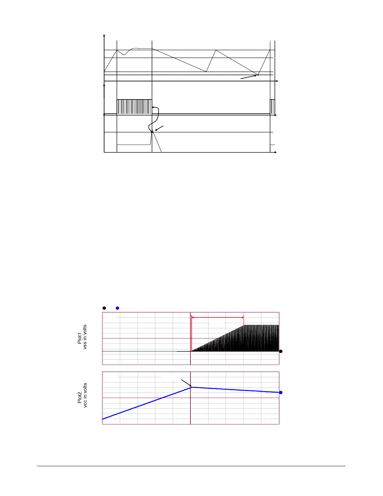
Soft−start
The Speedking II features an internal soft−start circuit
activated during the power on sequence (PON) but also in
fault recovery (short−circuit protection or brown−out
release). As soon as VCC reaches VCC(on), the peak current
is gradually increased from nearly zero up to the maximum
clamping level (e.g. 0.8 V/Rsense). The peak current is
clamped at 0.8 V/Rsense through the entire soft−start period
until the supply enters regulation. Figure 41 shows a typical
startup shot.
vss vcc
1.30 Ip(t)
900m
5 ms
500m
100m
1
−300m
13.0
12.0
8.56m
VCC
11.0
9.23m
9.90m
VCC(on)
10.6m
11.2m
2
10.0
9.00
7.95m
8.95m
9.95m
10.9m
11.9m
time in seconds
Figure 41. Soft−start is Activated During a Start−up Sequence, an
Auto−recovery Burst−mode or when the Brown−out Pin is Released
http://onsemi.com
19
Share Link: 