NTE1767 데이터 시트보기 (PDF) - NTE Electronics
부품명
상세내역
일치하는 목록
NTE1767 Datasheet PDF : 3 Pages
| |||
Electrical Characteristics: (VCC = 24V, TA = +25°C, RL = 8Ω, 9.4mH unless otherwise specified)
Parameter
Symbol Test Conditions Min Typ Max Unit
Power Supply Current
IOC
240 270 300 mA
Deflection Current
IDEF
1.9 2.0 2.1 AP–P
Neutral Point Potential
VODC
10 12 14 V
Flyback Pulse Voltage
RPV
46 49 54 V
Blanking Pulse Width
RPW
550 650 750 µs
Idling Current
IQ
8 16 24 mA
Voltage Booster Discharge Saturation Voltage VS6–7
– 1.8 2.4 V
Voltage Booster Charge Saturation Voltage
VS7–1
– 1.0 1.5 V
Voltage Booster Charge Current
I7
55 85 120 mA
Deflection Circuit Output Saturation Voltage
VS2–1
– 1.0 1.6 V
VS3–2
– 2.4 3.0 V
Deflection Circuit Input Saturation Voltage
V4
0.85 1.0 1.15 V
Voltage Gain
Input Resistance
Thermal Resistance, Junction–to–Case
AVO
Rin
RΘJC
– 55 – dB
– 22 – kΩ
– – 4.0 °C/W
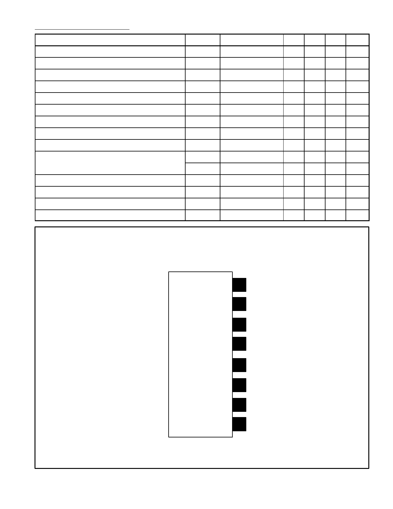
Pin Connection Diagram
(Front View)
8 N.C.
7 Voltage Booster Output
6 VCC
5 Capacitor for Preventing
Oscillation
4 Input
3
DPoewflee1crtifoonr
Vertical
Output
2 Deflection Output
1 GND
Share Link: 