RFD21815 데이터 시트보기 (PDF) - Unspecified
부품명
상세내역
일치하는 목록
RFD21815 Datasheet PDF : 7 Pages
| |||
© Copyright, RF Digital
10/15/2012 12:58 PM
RoHS CE • ESTI
RFD21815 FCC • IC
Approved & Certified
13715 Alton Pkwy • Irvine • CA • 92618
Tel: 949.610.0008 • www.RFdigital.com
Fast Answers: support@rfdigital.com
RFDP8
Shield for
Arduino
RFD21815
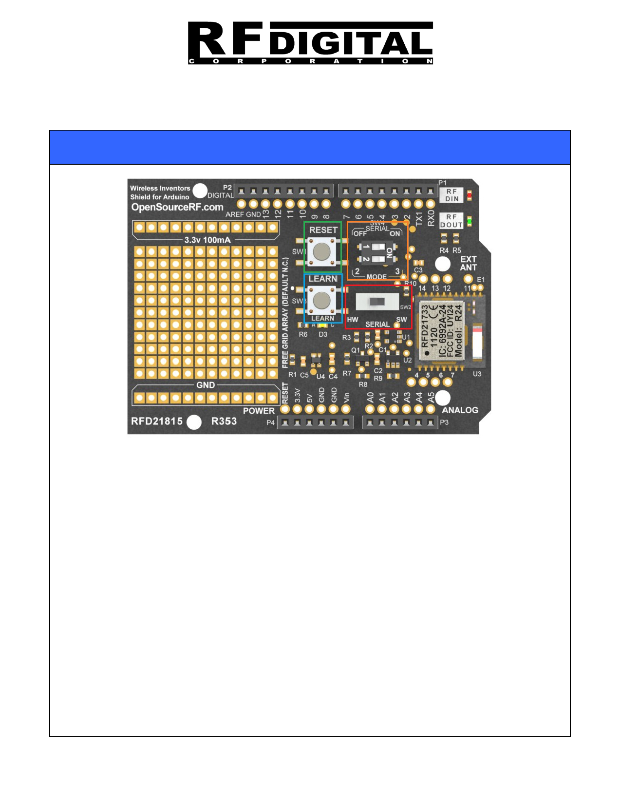
Setup
Reset Button (SW1) : This is tied to the Arduino and will reset the Arduino system
Serial Mode (SW4) Bank 1 : Enables the 5V/3V level translators for the serial
connection between the Wireless shield and the Arduino. This is useful when you want
to put the RX and TX lines in High-Z and electrically disconnect them from the
Arduino.
Serial Mode (SW4) Bank 2 : Sets the RF Mode of the RFD21733. In Mode 2, the
shield will receive data from any RFDP8 Wireless Pipe equipped module. In Mode 3,
the shield will only receive data from any RFDP8 Wireless Pipe equipped modules
which have been “Learned”. See the Network Mode section below.
Learn Button (SW3): This button is used only in Mode 3, when you want to only listen
to particular RFD21733 modules. See the Network Mode section below for more
details.
HW/SW Serial Switch (SW2): This switch allows you to connect the shield to either the
hardware serial pins of the Arduino D0 (Rx) and D1 (Tx) or the software serial pins
which in this case are D10 and D11. Refer to the schematic below for more details.
The RF DIN and RF DOUT led indicators are tied to the RX and TX lines and will blink
when data is sent or received.
2
Share Link: 