HM-6518-9 데이터 시트보기 (PDF) - Intersil
부품명
상세내역
일치하는 목록
HM-6518-9 Datasheet PDF : 7 Pages
| |||
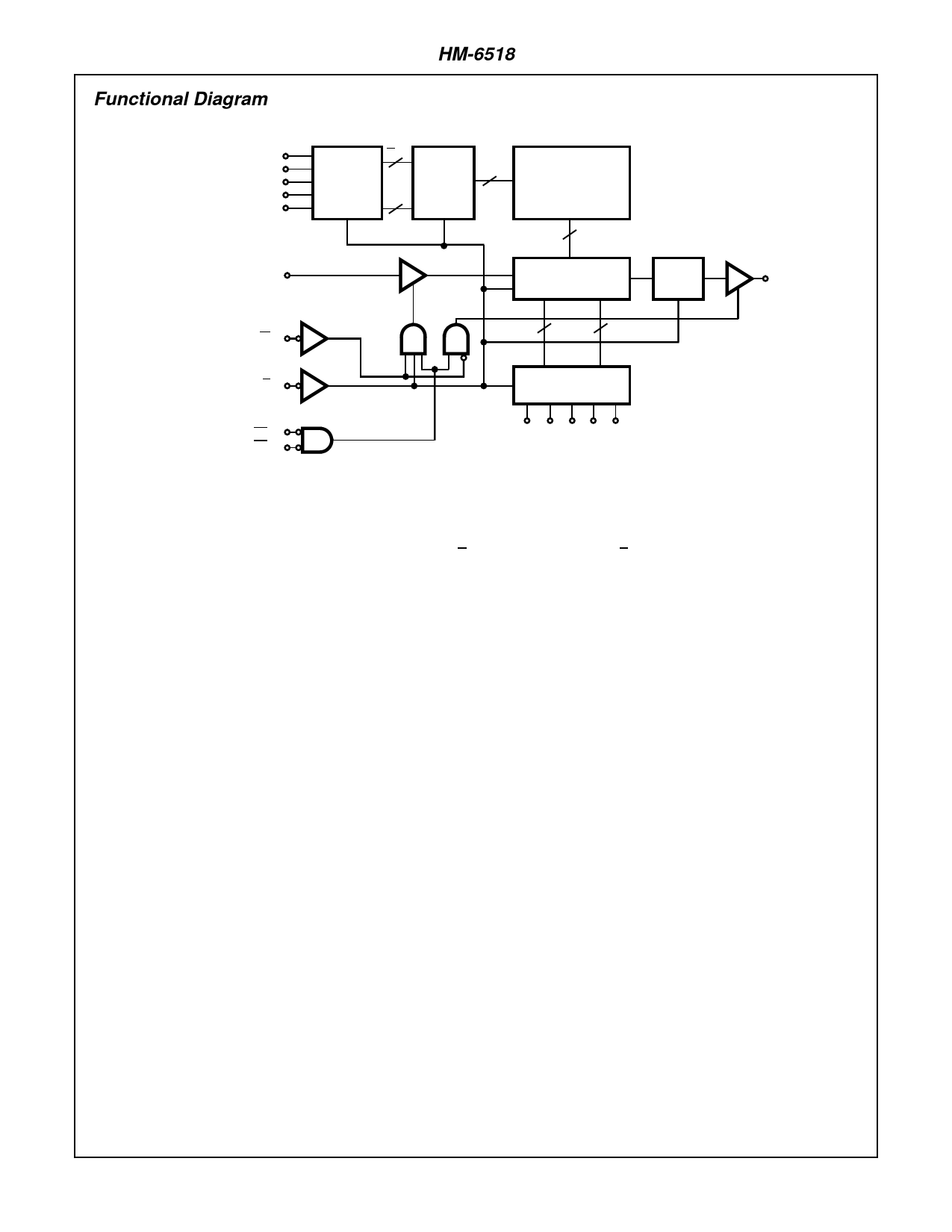
Functional Diagram
HM-6518
A5
A
A6
LATCHED 5 GATED
A7
A8
ADDRESS
ROW
REGISTER
DECODER 32
A
A9
5
G
32 x 32
MATRIX
32
D
GATED COLUMN D
Q
A
DECODER
AND DATA I/O
LATCH
Q
A
L
W
5
5
A
A
E
LATCHED ADDRESS
REGISTER
S1,
A0 A1 A2 A3 A4
S2
NOTES:
1. All lines positive logic - active high.
2. Three-state buffers: A high → output active.
3. Data latches: L high → Q = D; Q Latches on rising edge of L.
4. Address latches and gated decoders: Latch on falling edge of E and gate on falling edge of E.
6-2
Share Link: 