ICS670-01 데이터 시트보기 (PDF) - Integrated Circuit Systems
부품명
상세내역
일치하는 목록
ICS670-01 Datasheet PDF : 5 Pages
| |||
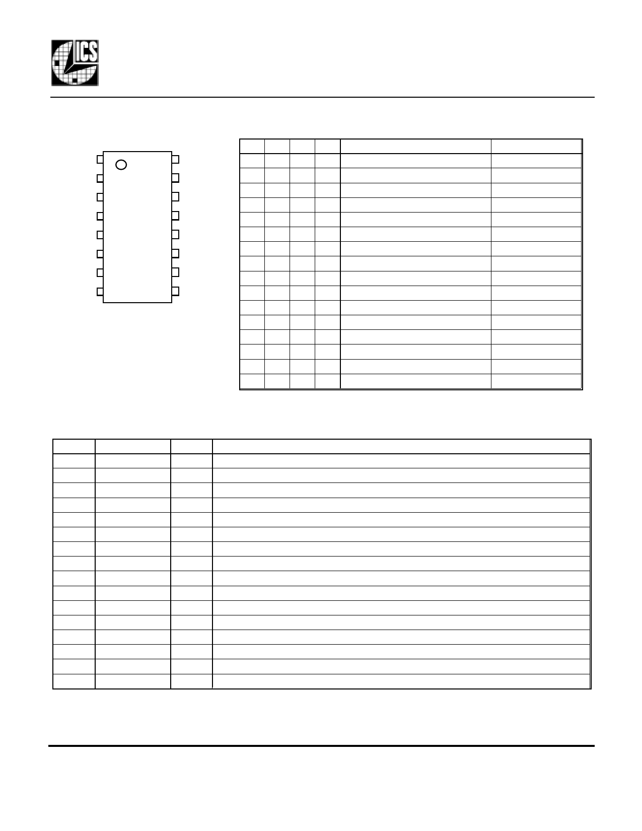
ICS670-01
Low Phase Noise Zero Delay Buffer and Multiplier
Pin Assignment
VDD 1
VDD 2
VDD 3
CLK2 4
OE2 5
FBCLK 6
OE1 7
FBIN 8
16 GND
15 GND
14 GND
13 S0
12 S1
11 S2
10 S3
9 ICLK
ICS670-01
Pin Descriptions
Multiplier Select Table
S3 S2 S1 S0
CLK2 (and FBCLK)
0 0 0 0 Low (Power down entire chip)
0001
Input x1.333
0010
Input x6
0011
Input x1.5
0100
Input x3.333
0101
Input x2.50
0110
Input x4
0111
Input x1
1000
Input x2.333
1001
Input x2.666
1010
Input x12
1011
Input x3
1100
Input x10
1101
Input x5
1110
Input x8
1111
Input x2
0=connect directly to ground
1=connect directl to VDD
Input Range (MHz)
-
18 - 120
5 - 26.67
16.67 - 107
7.5 - 48
10 - 64
6 - 40
25 - 160
11 - 69
10 - 60
5 - 13.33
8 - 53.33
5 - 16
6 - 32
5 - 20
12 - 80
Number
1
2
3
4
5
6
7
8
9
10
11
12
13
14
15
16
Name
VDD
VDD
VDD
CLK2
OE2
FBCLK
OE1
FBIN
ICLK
S3
S2
S1
S0
GND
GND
GND
Type
P
P
P
O
I
O
I
CI
CI
I
I
I
I
P
P
P
Description
Connect to +3.3V or +5V. Must match other VDDs.
Connect to +3.3V or +5V. Must match other VDDs.
Connect to +3.3V or +5V. Must match other VDDs.
Clock output from VCO. Output frequency equals the input frequency times multiplier.
Output clock enable 2. Tri-states the clock 2 output when low.
Clock ouput from VCO. Output frequency equals the input frequency times multiplier.
Output clock enable 1. Tri-states the feedback clock output when low.
Feedback clock input.
Clock input. Connect to a 5 - 160 MHz clock.
Multiplier select pin 3. Determines outputs per table above. Internal pull-up.
Multiplier select pin 2. Determines outputs per table above. Internal pull-up.
Multiplier select pin 1. Determines outputs per table above. Internal pull-up.
Multiplier select pin 0. Determines outputs per table above. Internal pull-up.
Connect to ground.
Connect to ground.
Connect to ground.
Key: I = Input with internal pull-up resistor; O = output; P = power supply connection; CI = clock input.
MDS 670-01 B
2
Revision 100900
Printed 11/15/00
Integrated Circuit Systems • 525 Race Street • San Jose •CA•95126•(408) 295-9800tel•http://www.icst.com
Share Link: 