T7234 데이터 시트보기 (PDF) - Agere -> LSI Corporation
부품명
상세내역
일치하는 목록
T7234 Datasheet PDF : 116 Pages
| |||
T7256 Single-Chip NT1 (SCNT1) Transceiver
Data Sheet
January 1998
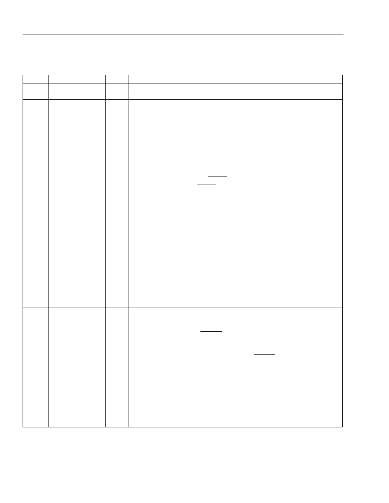
Pin Information (continued)
Table 1. Pin Descriptions
Pin
1, 10,
16
2
3
Symbol
GNDD
OPTOIN
STLED
Type*
Name/Function
— Digital Ground. Ground leads for digital circuitry.
Iu Optoisolator Input. Pin accepts CMOS logic level maintenance pulse
streams. These pulse streams typically are generated by an optoisolator
that is monitoring the U loop. Pulse patterns on this pin are digitally filtered
for 20 ms before being considered valid and are then decoded and interpret-
ed using the ANSI maintenance state machine requirements. If AUTOCTL
= 1 (register GR0, bit 3, default), the internal state machine decodes pulse
trains and implements the required maintenance states automatically. If AU-
TOCTL = 0, the pulse trains are decoded internally, but the microprocessor
must implement the maintenance state as indicated by the maintenance in-
terrupts (register MIR0). If the OPTOIN pin is being used for implementing
maintenance functions, the ILOSS pin should not be used (i.e., it should be
held high). Instead, the ILOSS register bit should be used (register CFR0,
bit 0). An internal 100 kΩ pull-up resistor is on this pin.
O Status LED Driver. Output pin for driving an LED (source/sink 4.0 mA) that
indicates the device status. The four defined states are low, high,
1 Hz flashing, and 8 Hz flashing (flashing occurs at 50% duty cycle). See the
STLED Description section for a detailed explanation of these states.
Also, this pin indicates device sanity upon power on/RESET, as follows:
s If AUTOACT/SCK = 0 (pin 15) after a device RESET (which sets AUTO-
ACT = 0 in register GR0 bit 6, turning on autoactivation), STLED will tog-
gle at an 8 Hz rate for at least 0.5 s, signifying an activation attempt. If the
activation attempt succeeds, it will continue to flash per the normal start-
up sequence (see STLED Description section).
s If AUTOACT/SCK = 1 (pin 15) after a device RESET, STLED will go low
for 1 s (flash of life), indicating that the device is operational, and no acti-
vation attempt will be made.
4 SYN8K/LBIND/FS O Synchronous 8 kHz Clock or Loopback Indicator. If TDMEN = 1 (register
GR2, bit 5, default), the pin function is determined based on the state of pin
12 (SYN8K_CTL/SDI) at the most recent rising edge of RESET. As SYN8K
(SYN8K_CTL/SDI = 0 at RESET rising edge), this pin is an 8 kHz 50% duty
cycle clock that is synchronous with the recovered timing from the U-inter-
face. When U-interface synchronization is not present, SYN8K is free-
running. As LBIND (SYN8K_CTL/SDI = 1 at RESET rising edge), this pin in-
dicates a 2B+D loopback:
0—No loopback.
1—eoc requested 2B+D loopback in progress.
Frame Strobe. If TDMEN = 0, this pin is a programmable strobe output used
to indicate appearance of B- and/or D-channel data on the TDM bus. Polar-
ity, offset, and duration of FS are programmable through the microprocessor
interface (see register TDR0). FS will be disabled until at least one of bits
2—7 in register DFR1 is enabled.
* Iu = input with internal pull-up.
6
Lucent Technologies Inc.
Share Link: 