NTE7150 데이터 시트보기 (PDF) - NTE Electronics
부품명
상세내역
일치하는 목록
NTE7150 Datasheet PDF : 8 Pages
| |||
Recommended Operating Conditions (Cont’d):
Parameter
Test Conditions
Video Input Signal Level
Composite Video Signal Amplitude
Chroma Input Signal Level
PAL/NTSC Chroma Input
SECAM Chroma Input
Sync Input Signal Level
Composite Video Signal Amplitude
Text Input Signal Level
FBP Width
FBP Input Current
RGB Output Current
H. Out Output Current
VP Output Current
Min Typ Max Unit
0.7 1.0 1.2 VP–P
100 200 300 mVP–P
50 100 150 mVP–P
1.0 2.0 2.5 VP–P
0.5 0.7 1.0 VP–P
11 12 13 µs
0.3 1.0 1.3 mA
– 1.0 2.0 mA
– 3.0 5.0 mA
– 1.0 2.0 mA
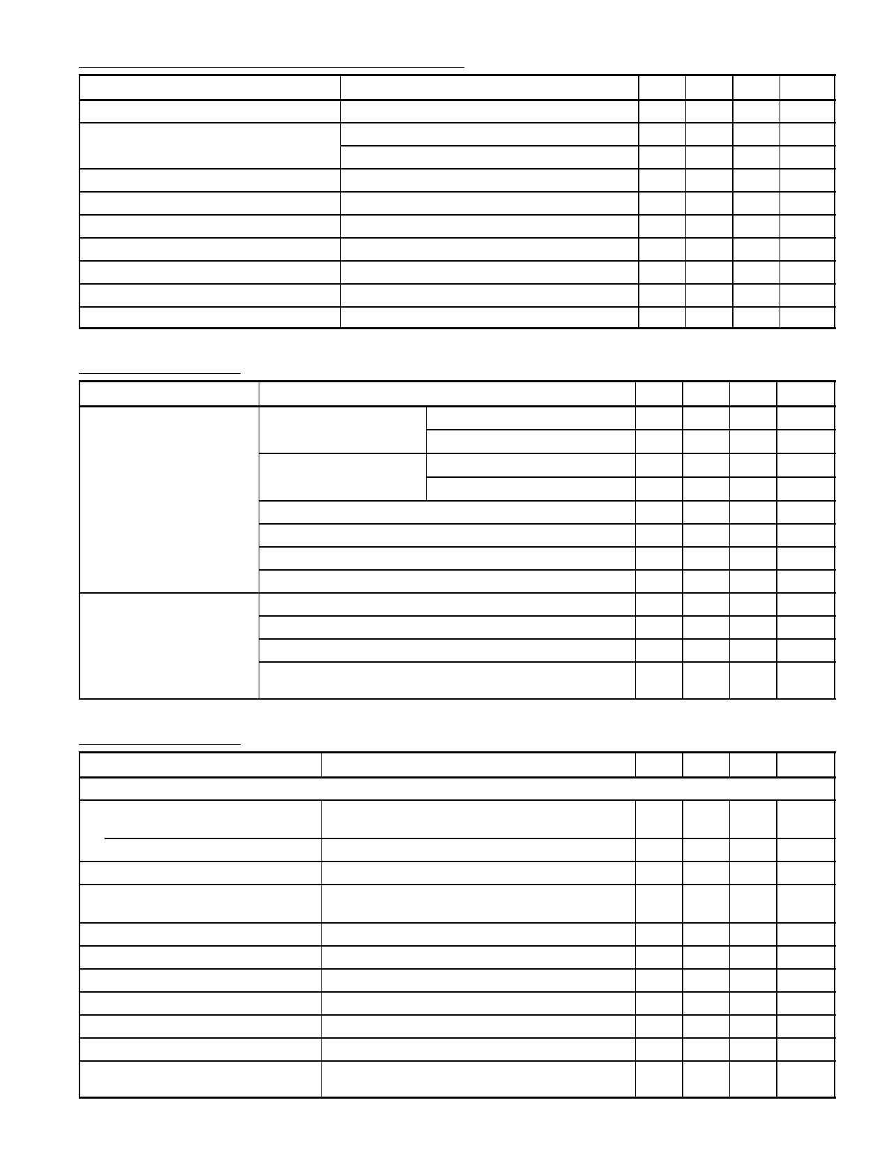
DC Characteristics: VCC = 9V, Logic VCC = 3.3V, TA = +25°C unless otherwise specified)
Parameter
Test Conditions
Min Typ Max Unit
Supply Current
Terminal Voltage
Logic VCC (Pin4) = 3.3V
10 20 28 mA
Video/Chroma VCC Turned OFF 15 30 40 mA
H. VCC (Pin5) = 9V
10 20 28 mA
Video/Chroma VCC Turned OFF 15 30 40 mA
TEXT Section VCC (Pin19) = 9V
15 31 44 mA
SECAM Section VCC (Pin36) = 9V
10 18 25 mA
Chroma Section VCC (Pin50) = 9V
12 27 38 mA
Video Section VCC (Pin59) = 9V
17 37 52 mA
Pin2
7.2 7.4 7.8
V
Pin16, Pin17, and Pin18 (In Mute Mode)
1.7 2.0 2.3
V
Pin22, Pin23, and Pin24 (Uni–Color DAC center)
3.3 3.8 4.2
V
Pin63 (Apply 5V with 5.1kΩ Resistor, Measure DC Output 3.1 3.5 3.9
V
Voltage at Trace Period)
AC Characteristics: VCC = 9V, Logic VCC = 3.3V, TA = +25°C unless otherwise specified)
Parameter
Test Conditions
Min Typ Max Unit
Video Section
Y Input Dynamic Range
Upper
Lower
Y Input Impedance
Measure dynamic range above the pedestal level 0.7 1.0 1.3 VP–P
Measure dynamic range below the pedestal level 0.0 0.3 0.5 VP–P
Measure input impedance of Pin60
100 130 –
kΩ
Y Input Clamp Voltage
Measure DC voltage at Pin60 when Y input
connected to AC GND.
2.5 2.8 3.1
V
Maximum Y Gain
15.0 17.5 23.0 dB
Y Frequency Bandwidth
8 10 15 MHz
Black Stretching Amp Maximum Gain
1.3 1.4 1.5
Black Stretching Start Point
40 50 65 IRE
DC Restoration Ratio
97 100 103 %
Black Stretching Start Voltage
3.2 3.3 3.6
V
Delay Time of Sharpness Circuit Measure difference in Y output signal delay time 115 125 135 ns
between sharpness SW turned ON and OFF.
Share Link: 