M74HC595RM13TR 데이터 시트보기 (PDF) - STMicroelectronics
부품명
상세내역
일치하는 목록
M74HC595RM13TR Datasheet PDF : 16 Pages
| |||
M74HC595
Symbol
Parameter
ts Minimum Set-up
Time
(SCRL - RCK)
th Minimum Hold
Time
tREM Minimum Clear
Removal Time
Test Condition
VCC CL
(V) (pF)
2.0
4.5 50
6.0
2.0
4.5 50
6.0
2.0
4.5 50
6.0
Value
TA = 25°C
-40 to 85°C -55 to 125°C Unit
Min. Typ. Max. Min. Max. Min. Max.
40 100
125
145
10 20
25
29 ns
7 17
21
25
0
0
0
0
0
0 ns
0
0
0
15 50
65
75
3 10
13
15 ns
3
9
11
13
CAPACITIVE CHARACTERISTICS
Test Condition
Value
Symbol
Parameter
VCC
(V)
TA = 25°C
-40 to 85°C -55 to 125°C Unit
Min. Typ. Max. Min. Max. Min. Max.
CIN Input Capacitance
5 10
10
10 pF
CPD Power Dissipation
Capacitance (note
184
pF
1)
1) CPD is defined as the value of the IC’s internal equivalent capacitance which is calculated from the operating current consumption without
load. (Refer to Test Circuit). Average operating current can be obtained by the following equation. ICC(opr) = CPD x VCC x fIN + ICC
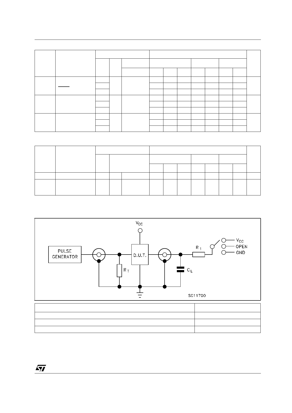
TEST CIRCUIT
TEST
tPLH, tPHL
tPZL, tPLZ
tPZH, tPHZ
CL = 50pF/150pF or equivalent (includes jig and probe capacitance)
R1 = 1KΩ or equivalent
RT = ZOUT of pulse generator (typically 50Ω)
SWITCH
Open
VCC
GND
7/16
Share Link: 