M38B57MFH-XXXXFP 데이터 시트보기 (PDF) - MITSUBISHI ELECTRIC
부품명
상세내역
일치하는 목록
M38B57MFH-XXXXFP Datasheet PDF : 355 Pages
| |||
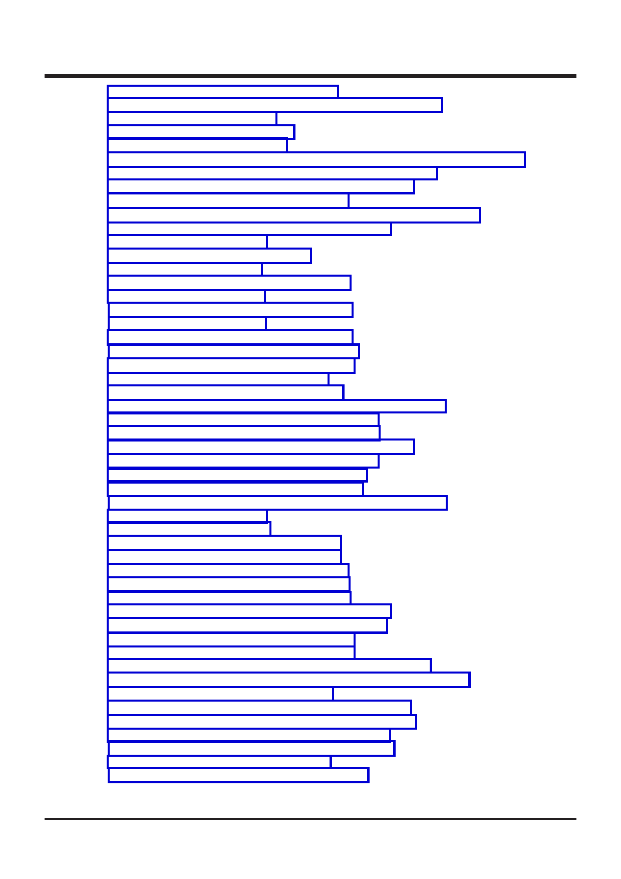
List of figures
Fig. 3.3.9 Status flag at decimal calculations .......................................................................... 3-23
Fig. 3.3.10 Programming and testing of One Time PROM version ...................................... 3-23
Fig. 3.4.1 Selection of packages ............................................................................................... 3-26
Fig. 3.4.2 Wiring for the RESET pin ......................................................................................... 3-26
Fig. 3.4.3 Wiring for clock I/O pins ........................................................................................... 3-27
Fig. 3.4.4 Wiring for the VPP pin of the One Time PROM and the EPROM version ......... 3-28
Fig. 3.4.5 Bypass capacitor across the VSS line and the VCC line ........................................ 3-28
Fig. 3.4.6 Analog signal line and a resistor and a capacitor ................................................ 3-29
Fig. 3.4.7 Wiring for a large current signal line ...................................................................... 3-29
Fig. 3.4.8 Wiring of signal lines where potential levels change frequently ......................... 3-30
Fig. 3.4.9 VSS pattern on the underside of an oscillator ........................................................ 3-30
Fig. 3.4.10 Setup for I/O ports ................................................................................................... 3-31
Fig. 3.4.11 Watchdog timer by software ................................................................................... 3-32
Fig. 3.5.1 Structure of port Pi .................................................................................................... 3-33
Fig. 3.5.2 Structure of port Pi direction register ...................................................................... 3-33
Fig. 3.5.3 Structure of port P6 ................................................................................................... 3-34
Fig. 3.5.4 Structure of port P6 direction register .................................................................... 3-34
Fig. 3.5.5 Structure of port P9 ................................................................................................... 3-35
Fig. 3.5.6 Structure of port P9 direction register .................................................................... 3-35
Fig. 3.5.7 Structure of PWM register (high-order) ................................................................... 3-36
Fig. 3.5.8 Structure of PWM register (low-order) .................................................................... 3-36
Fig. 3.5.9 Structure of baud rate generator ............................................................................. 3-37
Fig. 3.5.10 Structure of UART control register ........................................................................ 3-37
Fig. 3.5.11 Structure of serial I/O1 automatic transfer data pointer ..................................... 3-38
Fig. 3.5.12 Structure of serial I/O1 control register 1 ............................................................ 3-38
Fig. 3.5.13 Structure of serial I/O1 control register 2 ............................................................ 3-39
Fig. 3.5.14 Structure of serial I/O1 register/Transfer counter ................................................ 3-40
Fig. 3.5.15 Structure of serial I/O1 control register 3 ............................................................ 3-41
Fig. 3.5.16 Structure of serial I/O2 control register ................................................................ 3-42
Fig. 3.5.17 Structure of serial I/O2 status register ................................................................. 3-43
Fig. 3.5.18 Structure of serial I/O2 transmit/receive buffer register ..................................... 3-43
Fig. 3.5.19 Structure of timer i ................................................................................................... 3-44
Fig. 3.5.20 Structure of timer 2 ................................................................................................. 3-44
Fig. 3.5.21 Structure of PWM control register ......................................................................... 3-44
Fig. 3.5.22 Structure of timer 6 PWM register ........................................................................ 3-45
Fig. 3.5.23 Structure of timer 12 mode register ...................................................................... 3-45
Fig. 3.5.24 Structure of timer 34 mode register ...................................................................... 3-46
Fig. 3.5.25 Structure of timer 56 mode register ...................................................................... 3-46
Fig. 3.5.26 Structure of watchdog timer control register ........................................................ 3-47
Fig. 3.5.27 Structure of timer X (low-order, high-order) ......................................................... 3-47
Fig. 3.5.28 Structure of timer X mode register 1 .................................................................... 3-48
Fig. 3.5.29 Structure of timer X mode register 2 .................................................................... 3-49
Fig. 3.5.30 Structure of interrupt interval determination register .......................................... 3-49
Fig. 3.5.31 Structure of interrupt interval determination control register ............................. 3-50
Fig. 3.5.32 Structure of A-D control register ............................................................................ 3-50
Fig. 3.5.33 Structure of A-D conversion register (low-order) ................................................. 3-51
Fig. 3.5.34 Structure of A-D conversion register (high-order) ............................................... 3-51
Fig. 3.5.35 Structure of interrupt source switch register ........................................................ 3-52
Fig. 3.5.36 Structure of interrupt edge selection register ...................................................... 3-52
Fig. 3.5.37 Structure of CPU mode register ............................................................................ 3-53
Fig. 3.5.38 Structure of interrupt request register 1 ............................................................... 3-54
38B5 Group User’s Manual
vii
Share Link: 