LM2931 데이터 시트보기 (PDF) - Motorola => Freescale
부품명
상세내역
일치하는 목록
LM2931 Datasheet PDF : 16 Pages
| |||
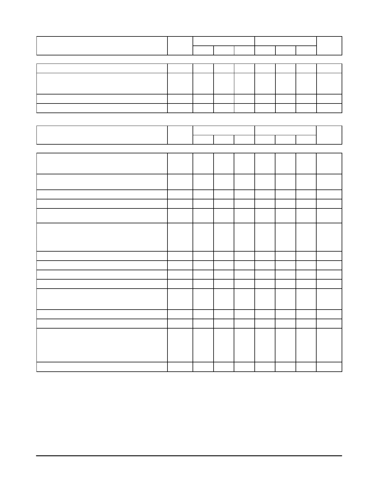
LM2931 Series
ELECTRICAL CHARACTERISTICS (Vin = 14 V, IO = 10 mA, CO = 100 µF, CO(ESR) = 0.3 Ω, TJ = 25°C [Note 1].)
LM2931–5.0
LM2931A–5.0
Characteristic
Symbol Min Typ Max Min Typ Max
Unit
FIXED OUTPUT
Ripple Rejection (f = 120 Hz)
RR
60
90
–
60
90
–
dB
Dropout Voltage
IO = 10 mA
IO = 100 mA
Over–Voltage Shutdown Threshold
VI–VO
V
–
0.015 0.2
–
0.015 0.2
–
0.16
0.6
–
0.16 0.6
Vth(OV) 26
29.5
40
26
29.5
40
V
Output Voltage with Reverse Polarity Input (Vin = –15 V)
–VO
– 0.3
0
–
– 0.3
0
–
V
ELECTRICAL CHARACTERISTICS (Vin = 14 V, IO = 10 mA, CO = 100 µF, CO(ESR) = 0.3 Ω, TJ = 25°C [Note 1].)
LM2931C
LM2931AC
Characteristic
Symbol Min Typ Max Min Typ Typ
ADJUSTABLE OUTPUT
Reference Voltage (Note 2, Figure 18)
IO = 10 mA, TJ = 25°C
IO ≤ 100 mA, TJ = – 40 to +125°C
Output Voltage Range
Vref
1.14 1.20 1.26 1.17 1.20 1.23
1.08
–
1.32 1.15
–
1.25
VOrange 3.0 to 2.7 to
–
3.0 to 2.7 to
–
24
29.5
24
29.5
Line Regulation (Vin = VO + 0.6 V to 26 V)
Load Regulation (IO = 5.0 mA to 100 mA)
Output Impedance
IO = 10 mA, ∆IO = 1.0 mA, f = 10 Hz to 10 kHz
Bias Current
IO = 100 mA
IO = 10 mA
Output Inhibited (Vth(OI) = 2.5 V)
Adjustment Pin Current
Output Noise Voltage (f = 10 Hz to 100 kHz)
Long–Term Stability
Regline
–
0.2
1.5
–
0.2
1.5
Regload
–
0.3
1.0
–
0.3
1.0
ZO
–
40
–
–
40
–
IB
–
6.0
–
–
6.0
–
–
0.4
1.0
–
0.4
1.0
–
0.2
1.0
–
0.2
1.0
IAdj
–
0.2
–
–
0.2
–
Vn
–
140
–
–
140
–
S
–
0.4
–
–
0.4
–
Ripple Rejection (f = 120 Hz)
RR
0.10 0.003
–
0.10 0.003
–
Dropout Voltage
IO = 10 mA
IO = 100 mA
Over–Voltage Shutdown Threshold
VI–VO
–
0.015 0.2
–
0.16
0.6
Vth(OV) 26
29.5
40
–
0.015
–
0.16
26
29.5
Output Voltage with Reverse Polarity Input (Vin = –15 V)
–VO
– 0.3
0
–
–0.3
0
Output Inhibit Threshold Voltages
Output “On”:
Output “Off”:
TJ = 25°C
TJ = – 40° to +125°C
TJ = 25°C
TJ = – 40° to +125°C
Output Inhibit Threshold Current (Vth(OI) = 2.5 V)
Vth(OI)
–
2.15 1.90
–
2.15
–
–
1.20
–
–
2.50 2.26
–
2.50 2.26
3.25
–
–
3.25
–
Ith(OI)
–
30
50
–
30
NOTES: 1. Low duty cycle pulse techniques are used during test to maintain junction temperature as close to ambient as possible.
2. The reference voltage on the adjustable device is measured from the output to the adjust pin across R1.
0.2
0.6
40
–
1.90
1.20
–
–
50
Unit
V
V
mV/V
%/V
mΩ/V
mA
µA
µVrms/V
%/kHR
%/V
V
V
V
V
µA
4
MOTOROLA ANALOG IC DEVICE DATA
Share Link: 