A2918 데이터 시트보기 (PDF) - Allegro MicroSystems
부품명
상세내역
일치하는 목록
A2918 Datasheet PDF : 8 Pages
| |||
2918
DUAL FULL-BRIDGE
PWM MOTOR DRIVER
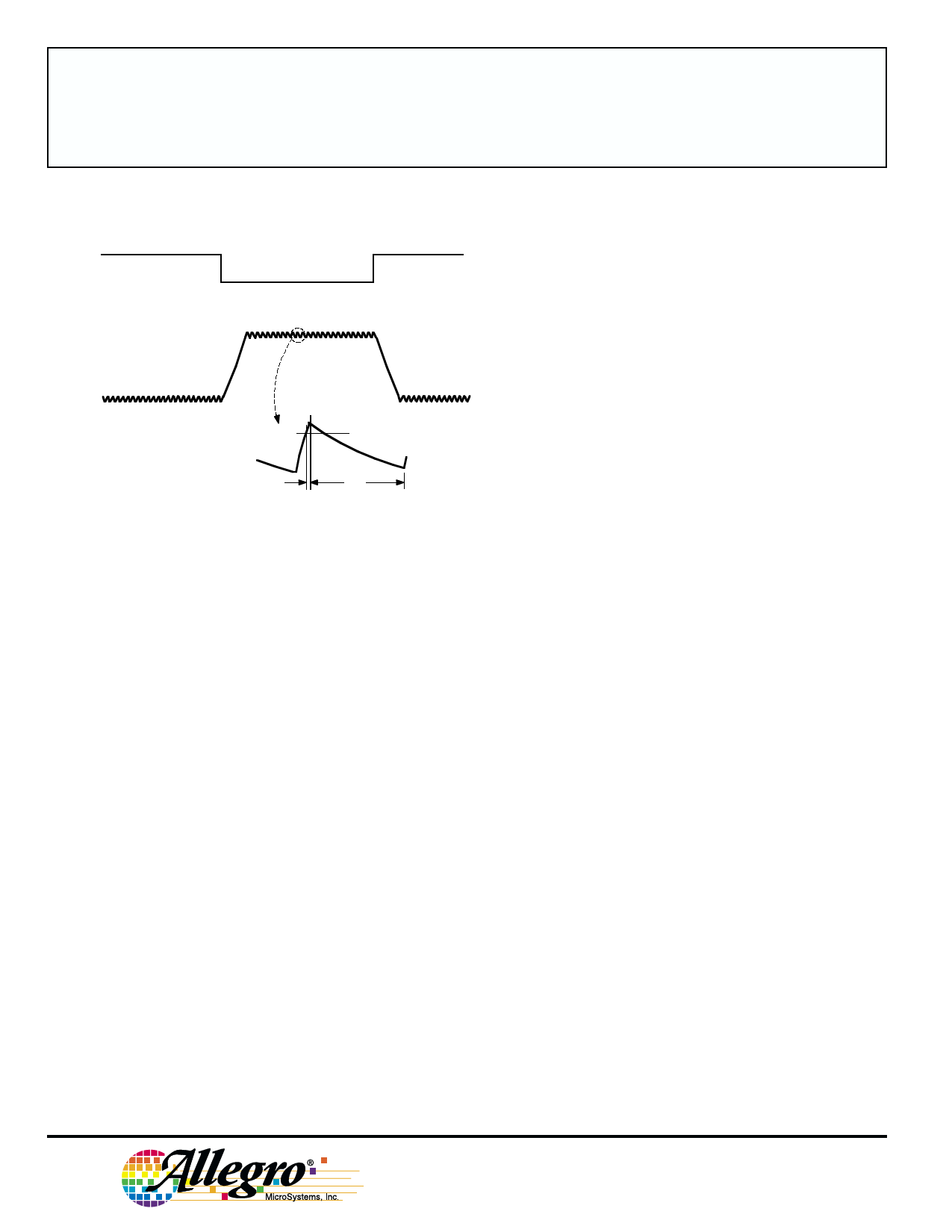
PWM OUTPUT CURRENT WAVEFORM
V PHASE
+
I OUT 0
–
I TRIP
td
toff
Dwg. WM-003-1A
APPLICATIONS INFORMATION
PWM Current Control
The A2918SWH/V dual bridges are
designed to drive both windings of a bipolar stepper
motor. Output current is sensed and controlled
independently in each bridge by an external sense
resistor (RS), an internal comparator, and an internal
monostable multivibrator.
When the bridge is turned ON, current increases
in the motor winding and it is sensed by RS until the
sense voltage (VSENSE) reaches the level set at the
comparator’s input:
ITRIP = VREF/10 RS
The comparator then triggers the monostable which
turns OFF the source driver of the bridge. The actual
load current peak will be slightly higher than the trip
point (especially for low-inductance loads) because of
internal logic and switching delays. This delay (td) is
2 µs typically. After turn-off, the motor current decays,
circulating through the ground clamp diode and sink
transistor. The source driver’s OFF time toff, and
therefore the magnitude of the current decrease, is
determined by the monostable’s external RC timing
components, where toff = RTCT within the range of 20
kΩ to 100 kΩ and 200 pF to 500 pF.
When the source driver is re-enabled, the winding
current (the sense voltage) again is allowed to rise to
the comparator’s threshold. This cycle repeats itself,
maintaining the average motor winding current at the
desired level.
Special circuitry has been included to prevent
runaway current control when toff is set too short.
This circuitry prevents the source driver from being
re-enabled until the load current has decayed to
below the ITRIP level.
Loads with high distributed capacitances may result
in high turn-ON current peaks. This peak, appearing
across RS, will attempt to trip the comparator, resulting
in possible erroneous current control or high-frequency
oscillations. An external RCCC low-pass filter may be
used to delay the action of the comparator, and thus
ignore turn-on spikes.
115 Northeast Cutoff, Box 15036
Worcester, Massachusetts 01615-0036 (508) 853-5000
Share Link: 