WM9713 데이터 시트보기 (PDF) - Wolfson Microelectronics plc
부품명
상세내역
일치하는 목록
WM9713 Datasheet PDF : 108 Pages
| |||
Pre-Production
WM9713L
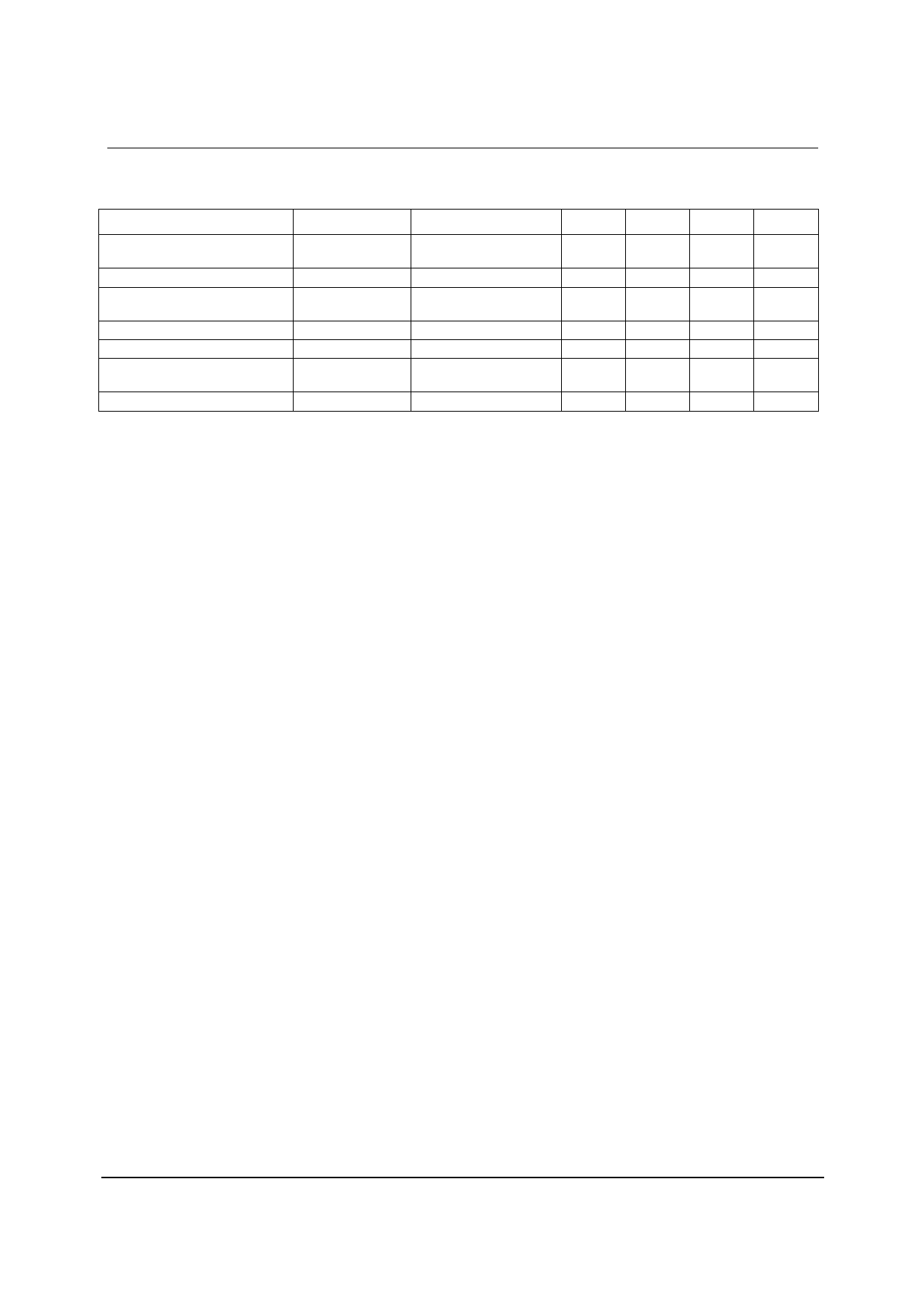
RECOMMENDED OPERATING CONDITIONS
PARAMETER
SYMBOL
Digital input/output buffer supply
range
Digital core supply range
Analogue supply range
Speaker supply range
Digital ground
Analogue ground
Difference AGND to DGND
DBVDD
DCVDD
AVDD, HPVDD,
TPVDD
SPKVDD
DGND1, DGND2
AGND, HPGND,
SPKGND, TPGND
Note:
1. AGND is normally the same as DGND1/DGND2
2. DCVDD <= DBVDD and DCVDD <= AVDD
3. DCVDD should be >=2V when using the PLL
TEST CONDITIONS
Note 1
MIN
1.71
1.71
1.8
1.8
-0.3
TYP
MAX
UNIT
3.3
3.6
V
1.8
3.6
V
3.3
3.6
V
3.3
4.2
V
0
V
0
V
0
+0.3
V
w
PP Rev 3.0 June 2006
7
Share Link: 