UPC8002GR-E1 데이터 시트보기 (PDF) - NEC => Renesas Technology
부품명
상세내역
일치하는 목록
UPC8002GR-E1 Datasheet PDF : 32 Pages
| |||
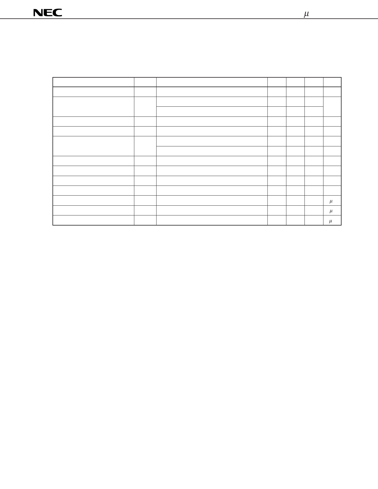
µPC8002
Electrical Specifications (TA = 25 °C, VCC = 3 V)
(1) Mixer Section (fMIX = 250 MHz, fLOC = 239.3 MHz, VLOC = –5 dBm) 0 dBm = 223.6 mVrms (at 50 Ω)
(Where not specified in the Test Condition, input has 50 Ω termination)
Parameter
Power supply current
Conversion gain
–1 dB compression output level
Third order intercept point
Noise factor
Local separation
Mixer input impedance
Local input impedance
Output resistance
Power-on rise time
Power-off fall time
Power-off power supply current
Symbol
Test Condition
ICCM No signal
GC 50 Ω resistance termination
LC matching (reference value)
VOM
IP3 Stipulated by output
NF
LC matching (reference value)
ISL
Mixer non-input
ZINM
ZINL
ROM
tONM
VPO = 3 VNote 3
tOFM
VPO = 0 VNote 4
ILM
VPO = 0 V
Note 1
Note 2
MIN. TYP. MAX.
1.7 2.2
4
8 11.0
17.0
–14 –10 –7
–3
16
7
40
54
31-j156
31-j169
230 330 430
8
15
1
3
0
5
Unit
mA
dB
dBm
dBm
dB
dB
dB
Ω
Ω
Ω
µs
µs
µA
Notes 1. f1 = 250.3 MHz, f2 = 250.6 MHz
2. Leakage from local input to mixer output
3. Time until the difference between the local input pin power-on and power-off voltages reaches 90 %
Power-on input voltage (VPO) rise time: 10 ns
4. Time until the power supply current reaches 10 % of the power-on value
Power-on input voltage (VPO) fall time: 10 ns
11
Share Link: 