GMS87C1404 데이터 시트보기 (PDF) - Hyundai Micro Electronics
부품명
상세내역
일치하는 목록
GMS87C1404 Datasheet PDF : 84 Pages
| |||
GMS87C1404/GMS87C1408
HYUNDAI MicroElectronics
8. MEMORY ORGANIZATION
The GMS87C1404 and GMS87C1408 have separate ad-
dress spaces for Program memory and Data Memory. Pro-
gram memory can only be read, not written to. It can be up
8.1 Registers
This device has six registers that are the Program Counter
(PC), a Accumulator (A), two index registers (X, Y), the
Stack Pointer (SP), and the Program Status Word (PSW).
The Program Counter consists of 16-bit register.
PCH
A
X
Y
SP
PCL
PSW
ACCUMULATOR
X REGISTER
Y REGISTER
STACK POINTER
PROGRAM COUNTER
PROGRAM STATUS
WORD
Figure 8-1 Configuration of Registers
Accumulator: The Accumulator is the 8-bit general pur-
pose register, used for data operation such as transfer, tem-
porary saving, and conditional judgement, etc.
The Accumulator can be used as a 16-bit register with Y
Register as shown below.
Y
Y
A
A
Two 8-bit Registers can be used as a “YA” 16-bit Register
Figure 8-2 Configuration of YA 16-bit Register
X, Y Registers: In the addressing mode which uses these
index registers, the register contents are added to the spec-
ified address, which becomes the actual address. These
modes are extremely effective for referencing subroutine
tables and memory tables. The index registers also have in-
crement, decrement, comparison and data transfer func-
tions, and they can be used as simple accumulators.
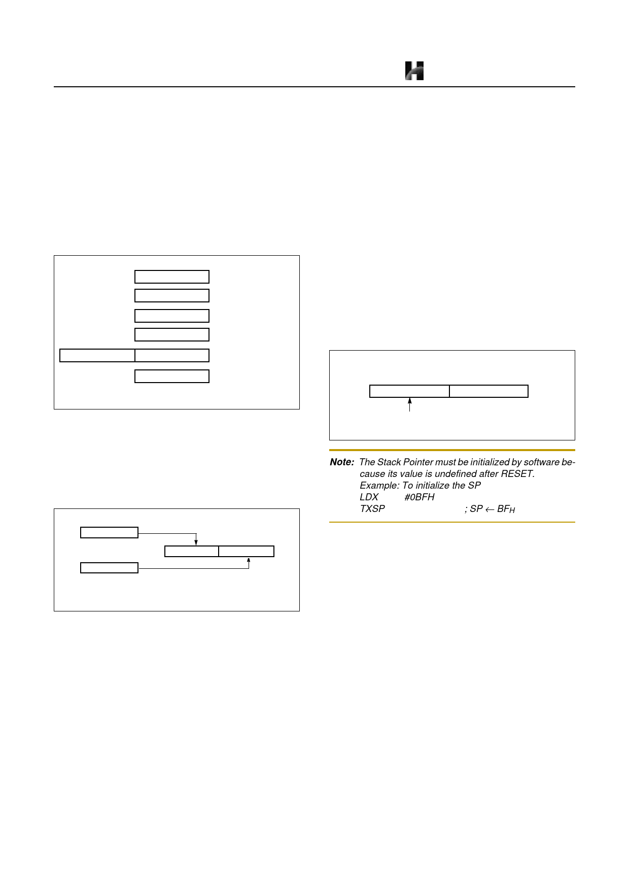
Stack Pointer: The Stack Pointer is an 8-bit register used
for occurrence interrupts and calling out subroutines. Stack
Pointer identifies the location in the stack to be accessed
(save or restore).
to 4K /8K bytes of Program memory. Data memory can be
read and written to up to 192 bytes including the stack area.
Generally, SP is automatically updated when a subroutine
call is executed or an interrupt is accepted. However, if it
is used in excess of the stack area permitted by the data
memory allocating configuration, the user-processed data
may be lost.
The stack can be located at any position within 00H to BFH
of the internal data memory. The SP is not initialized by
hardware, requiring to write the initial value (the location
with which the use of the stack starts) by using the initial-
ization routine. Normally, the initial value of “BFH” is
used.
Stack Address (000H ~ 0BFH)
15
87
0
0
SP
Hardware fixed
Note: The Stack Pointer must be initialized by software be-
cause its value is undefined after RESET.
Example: To initialize the SP
LDX
#0BFH
TXSP
; SP ← BFH
Program Counter: The Program Counter is a 16-bit wide
which consists of two 8-bit registers, PCH and PCL. This
counter indicates the address of the next instruction to be
executed. In reset state, the program counter has reset rou-
tine address (PCH:0FFH, PCL:0FEH).
Program Status Word: The Program Status Word (PSW)
contains several bits that reflect the current state of the
CPU. The PSW is described in Figure 8-3 . It contains the
Negative flag, the Overflow flag, the Break flag the Half
Carry (for BCD operation), the Interrupt enable flag, the
Zero flag, and the Carry flag.
[Carry flag C]
This flag stores any carry or borrow from the ALU of CPU
after an arithmetic operation and is also changed by the
Shift Instruction or Rotate Instruction.
[Zero flag Z]
This flag is set when the result of an arithmetic operation
or data transfer is “0” and is cleared by any other result.
16
Oct. 1999 Ver 1.0
Share Link: 