TEA7092TQ 데이터 시트보기 (PDF) - STMicroelectronics
부품명
상세내역
일치하는 목록
TEA7092TQ Datasheet PDF : 24 Pages
| |||
TEA7092
TRANSMIT CHARACTERISTICS (continued)
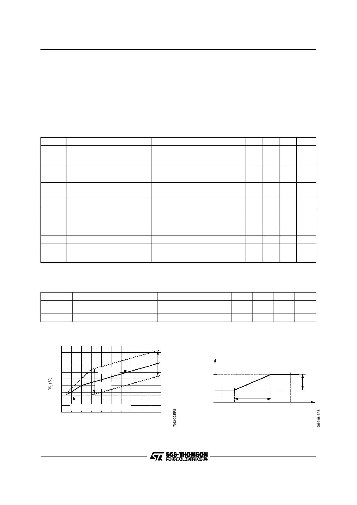
Maximum Level on Line in Tx (see Figure 3)
The minimum operating voltage of the TEA7092 is 2.5V. At low line current value, when the voltage over
the TEA7092 is low, the softclipping function automatically limits the AC dynamic to avoid to reach the 2.5V
limit on the TEA7092.
When the DC voltage over the TEA7092 is high enough, the AC dynamic is limited at a value fixed by the
external resistor RSOFT connected on Pin SOFTL.
The Value of RSOFT is performed by : RSOFT = (RS x 50E-6 - 0.8 - VacPeak) / 40E-6
Tx Characteristics (Tamb = 25°C, f = 1kHz, see Test 3)
Symbol
Parameter
Test Conditions
Min.
Transmit gain in Handset Mode
Vem = -48dBV
Gtl
IL = 20mA
44
Gtsm
IL = 90mA
37
Transmit gain in Handsfree Mode Vhfin = -28dBV, Code 0110010
Ghl
IL = 20mA
24
Ghfm
IL = 90mA
17
Gt-6dB Transmit Gain
Vem = -48dBV, IL = 20mA
5
(-6dB in transmit path)
Code 0110110
Zmic
Zhf
Ntx
Nhf
Mmic
VLpeak
Dtx1
Dtx2
Handset Mic Input Impedance
Between Pins MIC1, MIC2
30
Handsfree Mic Input Impedance Between HFIN and VREF
15
IL = 20mA, Code 0110010
Transmit Noise in Handset Mode
2kΩ between MIC1 & MIC2
Transmit Noise in Handsfree Mode
2kΩ between HFIN & VREF
Microphone Mute
Vem = -48dBV, IL = 20mA
60
Transmit Softclipping Level
See Figure 2, Vem = -42dBV, IL = 20mA 1.0
Transmit Distortion
IL = 20mA, see Figure 2
Vem = -48dBV
Vem = -36dBV
Typ.
45
39
25
19
6
40
20
-75
-75
1.4
Max. Unit
46 dB
41 dB
26 dB
21 dB
7
dB
50 kΩ
25 kΩ
dBmp
dBmp
dB
1.8 Vpeak
1
%
5
%
Squelch on Transmit Channel (Tamb = 25°C, f = 1kHz, IL = 20mA, see Test3)
The principle of the squelch is to reduce the transmit gain as soon as the amplitude of the signal on the
microphone is lower than a fixed threshold voltage, VT2.
Symbol
Gtlmax
Gtlmax-Gsq
Gsq
Parameter
Transmit Gain
Gain Variation
Test Conditions
Vem1 = -75dBV
Vem2 = -65dBV
See Figure 4 /
Min. Typ. Max. Unit
36
dB
45
dB
9
dB
Figure 3 : Line Peak Voltage versus DC Line
Current
10
8
VAC Pe ak
6
DC Mas k
4
VAC Peak
2
2.5V Min. Line Pe a k Voltag e
0
20
40
60
80
100
IL (mA)
Figure 4 : Transmit Gain versus Microphone
AC Input Signal
Tra ns mit
Gain (dB)
Gtlmax
Gtlmax - Gs q
Dgt
Ve m1 VT1
VT2
Vem2
Microphone AC Voltage
Gst
Ve m
(dBV)
7/24
Share Link: 