TA8002 데이터 시트보기 (PDF) - Toshiba
부품명
상세내역
일치하는 목록
TA8002 Datasheet PDF : 9 Pages
| |||
TA8002S/AS
FUNCTIONAL DESCRIPTION
The TA8002S / AS incorporates a constant-voltage 5V power supply function to feed the 5V logic circuits and a
reset function to ensure stable operation of the system. These functions are explained below.
(1) Constant-voltage 5V power supply function
This constant-voltage function has the reference voltage Vref in the IC that is insusceptible to
temperature changes and input voltage fluctuations. The power supply circuit is designed in such a way
that this voltage is stepped up to 5V by using an OP amp and a voltage-dividing resistor. These OP amp
and dividing resistor and an output transistor connected to the OP amp output together configure a
closed loop.
The output voltage of 5V is obtained by shorting the ADJ pin to GND. The output voltage is reduced to
3.5V by leaving this pin open, allowing for a further reduction in the amount of current consumed by the
entire system during standby.
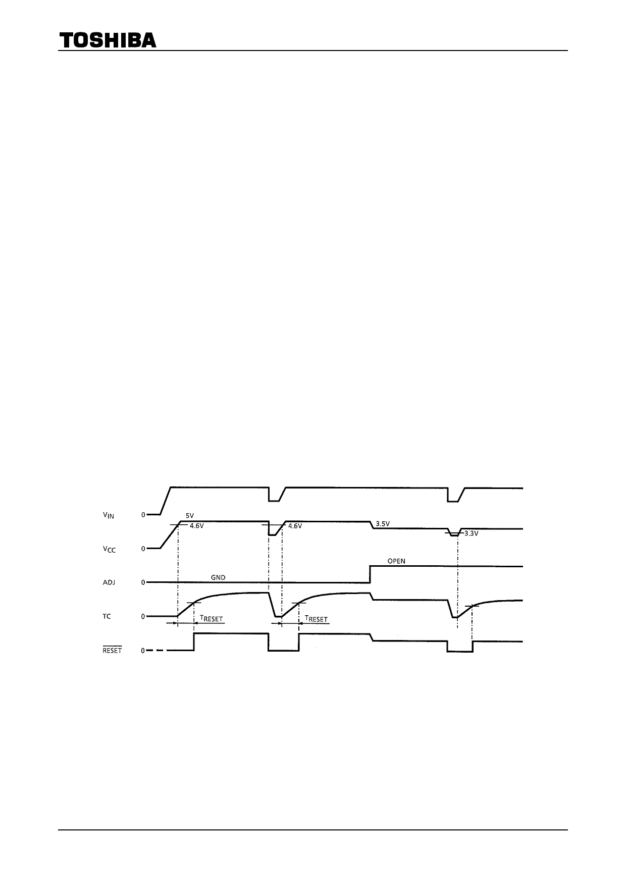
(2) System reset function (See Timing Chart)
· Voltage monitoring function
When powered on, the power-on reset timer starts counting the moment the voltage VCC applied to
the CPU exceeds 4.6V. When powered off, this voltage monitoring function outputs a reset signal
immediately when VCC drops below 4.6V. A reset signal also is output immediately when VCC drops
for some reason during normal operation. Then, when VCC is restored to the normal voltage and
exceeds 4.6V, the power-on reset timer starts counting.
· Power-on reset timer function
To allow the 5V constant voltage to stabilize at power-on, as well as prevent the circuit system from
operating erratically at power-on, the device remains reset for a predetermined time before being
released from the reset state. The duration of this time can be set as desired by choosing appropriate
values for the external resistor and capacitor connected to the TC pin.
The system starts charging the capacitor when the VCC voltage exceeds 4.6V. When this charging
voltage exceeds 1.7V, the reset signal is inverted to deactivate the reset.
TIMING CHART
Note: TRESET : Reset timer time
3
2002-03-12
Share Link: 