SS6639 데이터 시트보기 (PDF) - Silicon Standard Corp.
부품명
상세내역
일치하는 목록
SS6639 Datasheet PDF : 12 Pages
| |||
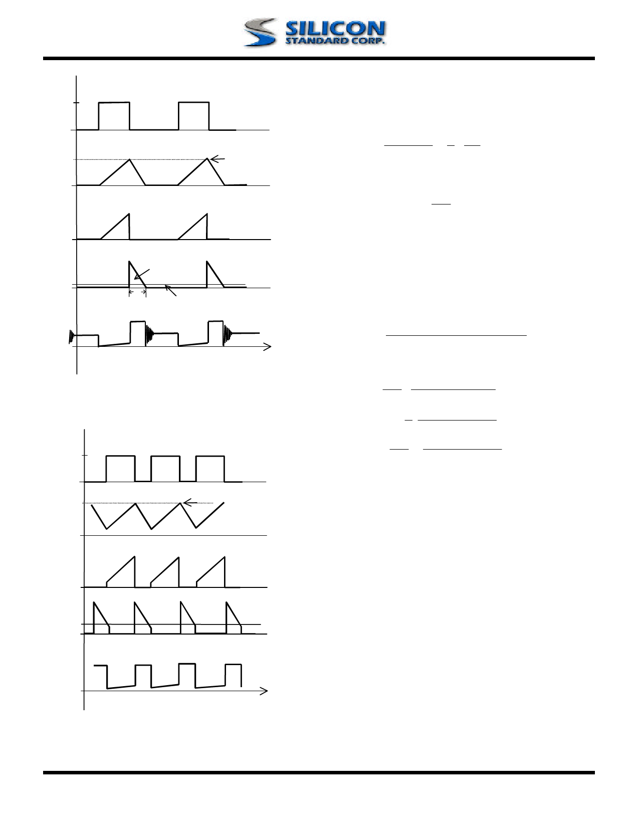
VEXT
IIN
IPK
ISW
Charge Co.
ID
IOUT
TDIS Discharge Co.
VSW
t
Discontinuous Conduction Mode
VEXT
IIN
IPK
SS6639
At the boundary between continuous and
discontinuous modes, the output current (IOB) is
determined by
IOB = VIN * 1 * VIN * TON * (1 − x)
VOUT + VD 2 L
where VD is the diode drop,
X = (RON + RS) ∗ TON
L
RON= Switch turn on resistance, RS= Inductor DC
resistance
TON = Switch ON time
In the discontinuous mode, the switching frequency
(Fsw) is
FSW
=
2(L) * (VOUT +
VIN 2
VD − VIN) * (IOUT)
* TON2
* (1+
x)
In the continuous mode, the switching frequency is
fsw = 1 * ( ) VOUT + VD − VIN
TON (VOUT + VD − VSW)
* [1 + x ( VIN − VSW )]
2 VOUT + VD − VSW
≅ 1 * VOUT + VD − VIN
TON VOUT + VD − VSW
where Vsw = switch drop and is proportional to
output current.
ISW
ID
VSW
IOUT
t
Continuous Conduction Mode
INDUCTOR SELECTION
To operate as an efficient energy transfer element,
the inductor must fulfill three requirements. First, the
inductance must be low enough for the inductor to
store adequate energy under the worst case
condition of minimum input voltage and switch ON
time. Second, the inductance must also be high
enough so the maximum current rating of the
SS6639 and the inductor are not exceeded at the
other worst case condition of maximum input voltage
and ON time. Lastly, the inductor must have
sufficiently low DC resistance so excessive power is
not lost as heat in the windings. Unfortunately this is
inversely related to physical size.
Rev.2.01 6/26/2003
www.SiliconStandard.com
9 of 12
Share Link: 