AK2500B 데이터 시트보기 (PDF) - Asahi Kasei Microdevices
부품명
상세내역
일치하는 목록
AK2500B Datasheet PDF : 17 Pages
| |||
ASAHI KASEI
[AK2500B]
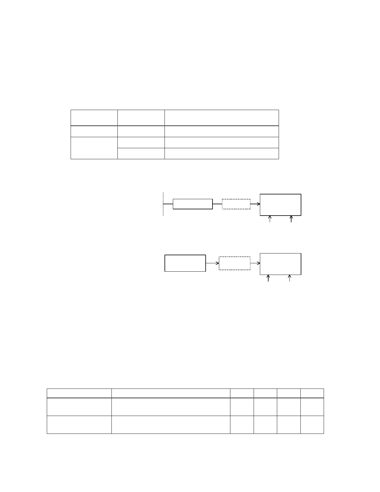
Equalizer Bypass
If the incoming signal is attenuated by flat loss only (zero cable loss), the internal equalizer should be bypassed
with MODE1=1, MODE2=1. (See Table 4) The level of the incoming signal should satisfy the RIN input range
(50mVpk - 1000mVpk for DS3/STS-1).
Table 4. Mode Control
MODE2
(pin24)
0
1
MODE1
(pin23)
0
OPEN
1
Function
Equalizer Enable
TEST MODE (Factory use only)
Equalizer Bypass
DSX-3
(1)Cable loss 0 - 450feet
+ Flat loss
Cable
0 - 450feet
Flat Loss
0 - 6dB
AK2500B
MODE2 MODE1
0
0
Equalizer enable
(2)Flat loss only
Transmitter
Flat Loss
Monitoring
circuit
AK2500B
MODE2 MODE1
1
1
Equalizer bypass
Fig. 1 AK2500B Application
Clock Acquisition
If a valid input signal is assumed to be already present at the analog input, the maximum time between the
application of device power and error-free operation is typically 20 ms.
Table 5. PLL Lock Acquisition Time
(TA = Tmin to Tmax; V+ = 3.3V±0.3V; GND = 0V)
Conditions
Power up
Power : Off -> On
Input data : Valid
Input data restore
Power : On
Input data : Loss -> Valid
min typ Max Units
20
ms
1.0 5.0 ms
MS0005-E-00
-6-
1999/12
Share Link: 