SB15 데이터 시트보기 (PDF) - TSC Corporation
부품명
상세내역
일치하는 목록
SB15 Datasheet PDF : 2 Pages
| |||
SB 15, 25, 35 SERIES
High Current 15, 25, 35 AMPS. Single Phase Bridge Rectifiers
Voltage Range
50 to 1000 Volts
Current
15.0/25.0/35.0 Amperes
Features
UL Recognized File # E-96005
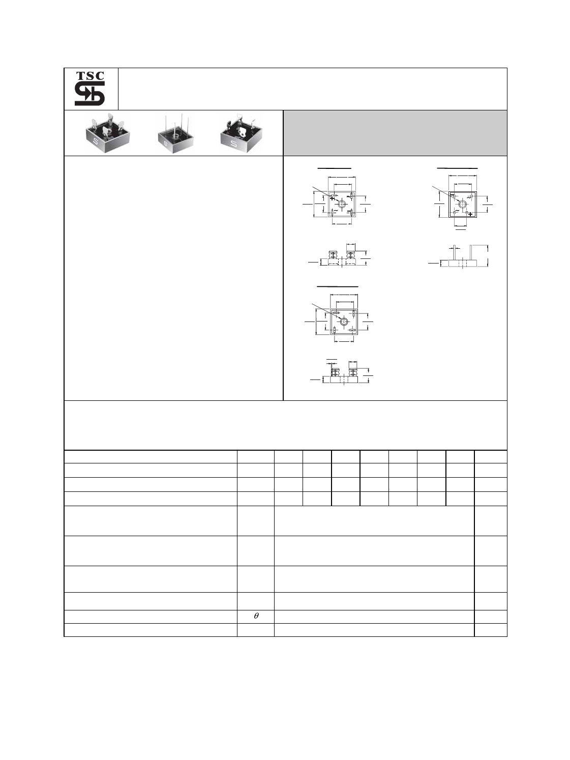
SB35
DIA .193(4.9)
HOLE FOR #8 SCREW
1.14(29.0)
1.01(25.7)
.692(17.6)
.612(15.5)
AC
SB35-W
DIA .193(4.9)
HOLE FOR #8 SCREW
1.14(29.0)
1.01(25.7)
.752(19.1)
.672(17.1)
Glass passivated junction
1.14(29.0) .692(17.6)
1.01(25.7) .612(15.5)
.602(15.3)
.522(13.3)
1.14(29.0)
1.01(25.7)
.752(19.1)
.672(17.1)
Metal case with an electrically isolated
.752(19.1)
.672(17.1)
epoxy
.490(12.4)
.410(10.4)
Rating to 1,000V PRV.
High efficiency
Mounting: thru hole for #8 screw
High temperature soldering guaranteed:
260℃ / 10 seconds at 5 lbs., ( 2.3 kg )
tension
.25(6.35)
.442(11.23)
.432(10.97)
.93(23.5)
.81(20.5)
SB35-M
DIA .193(4.9)
HOLE FOR #8 SCREW
1.14(29.0)
1.01(25.7)
.692(17.6)
.612(15.5)
.040(1.0)
DIA TYP
.442(11.23)
.432(10.97)
1.2(30.5)
MIN.
Leads solderable per MIL-STD-202
Method 208
Isolated voltage from case to lead over
2000 volts
1.14(29.0) .692(17.6)
1.01(25.7) .612(15.5)
.692(17.6)
.612(15.5)
.692(17.6)
.612(15.5)
.034(0.86)
.030(0.76)
.25(6.35)
.442(11.23)
.432(10.97)
.93(23.5)
.81(20.5)
Dimensions in inches and (millimeters)
Maximum Ratings and Electrical Characteristics
Rating at 25℃ambient temperature unless otherwise specified.
Single phase, half wave, 60 Hz, resistive or inductive load.
For capacitive load, derate current by 20%
Type Number
Symbol -05 -1 -2 -4 -6 -8 -10 Units
Maximum Recurrent Peak Reverse Voltage
VRRM 50 100 200 400 600 800 1000 V
Maximum RMS Voltage
VRMS 35 70 140 280 420 560 700 V
Maximum DC Blocking Voltage
VDC 50 100 200 400 600 800 1000 V
Maximum Average Forward
SB15
15.0
Rectified Current
SB25
I(AV)
25.0
A
@TC= 55℃
SB35
35.0
Peak Forward Surge Current,
SB15
200
Single Sine-wave Superimposed on SB25
Rated Load (JEDEC method )
SB35
IFSM
300
400
A
Maximum Instantaneous Forward
Voltage Drop Per Element
SB15 7.5A
SB25 12.5A
VF
at Specified Current
SB35 17.5A
1.1
V
Maximum DC Reverse Current
at Rated DC Blocking Voltage Per Element
IR
10
uA
Typical Thermal Resistance (Note 1)
RθJC
2.0
℃/W
Operating and Storage Temperature Range
TJ ,TSTG
- 50 to + 125 / -50 to +150
℃
Notes: 1. Thermal Resistance from Junction to Case.
2. Suffix “W” - Wire Lead Structure/”M” - Terminal Location Face to Face.
- 614 -
Share Link: 