PT6313-S 데이터 시트보기 (PDF) - Princeton Technology
부품명
상세내역
일치하는 목록
PT6313-S Datasheet PDF : 20 Pages
| |||
VFD Driver/Controller IC
Tel: 886-2-66296288
Fax: 886-2-29174598
URL: http://www.princeton.com.tw
PT6313-S
FUNCTION DESCRIPTION
COMMANDS
Commands determine the display mode and status of PT6313-S. A command is the first byte (b0 to b7)
inputted to PT6313-S via the DIN Pin after STB Pin has changed from “HIGH” to “LOW” State. If for
some reason the STB Pin is set to “HIGH” while data or commands are being transmitted, the serial
communication is initialized, and the data/commands being transmitted are considered invalid.
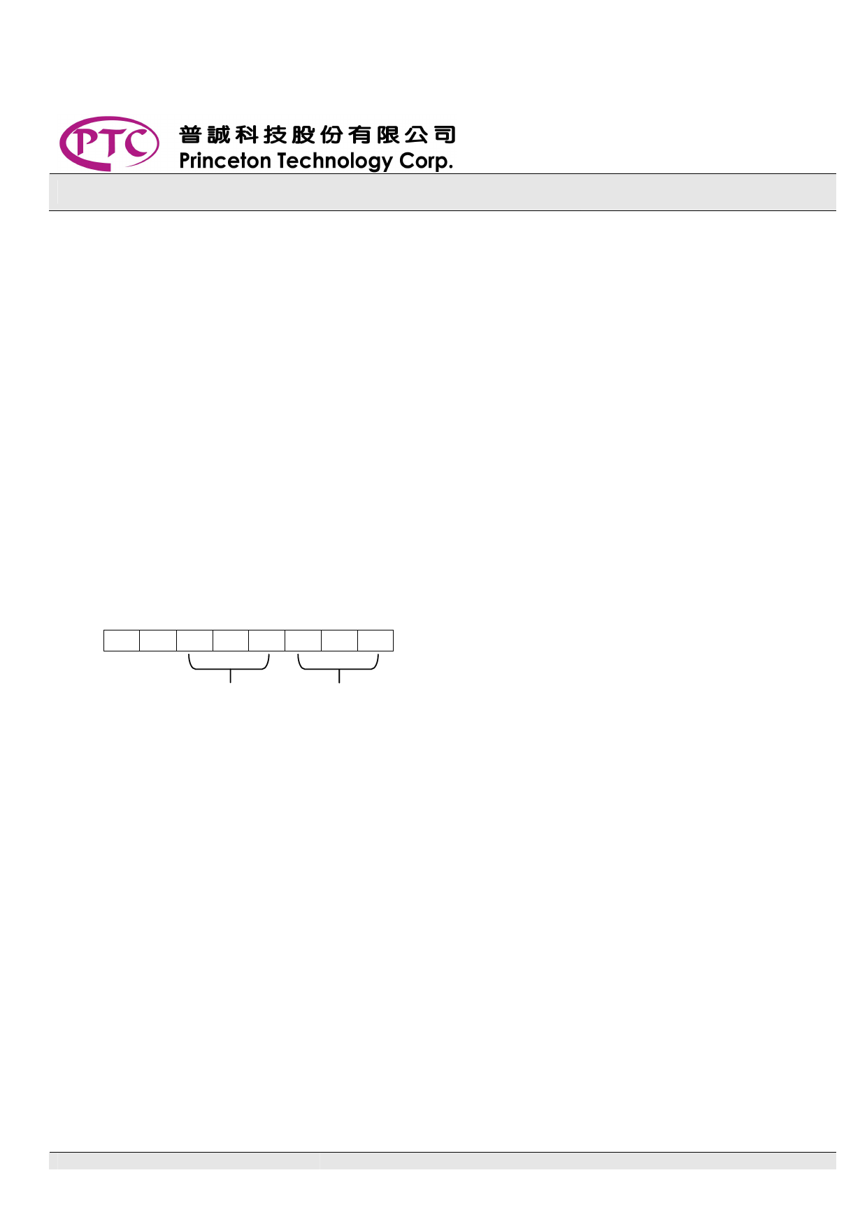
COMMAND 1: DISPLAY MODE SETTING COMMANDS
PT6313-S provides 4 display mode settings as shown in the diagram below: As stated earlier a
command is the first one byte (b0 to b7) transmitted to PT6313-S via the DIN Pin when STB is “LOW”.
However, for these commands, the bits 4 to 6 (b3 to b5) are ignored, bits 7 & 8 (b6 to b7) are given a
value of “0”.
The Display Mode Setting Commands determine the number of segments and grids to be used (1/4 to
1/8 duty, 12 to 8 segments).
When Power is turned “ON”, the 8-digit, 8-segment mode is selected.
MSB
LSB
0 0 - - - b2 b1 b0
Not Relevant
Display Mode Settings:
000: 4 digits, 12 segments
001: 5 digits, 11 segments
010: 6 digits, 10 segments
011: 7 digits, 9 segments
100: 8 digits, 8 segments
PT6313-S V1.2
-5-
September, 2005
Share Link: 