DG529 데이터 시트보기 (PDF) - Maxim Integrated
부품명
상세내역
일치하는 목록
DG529 Datasheet PDF : 12 Pages
| |||
8-Channel Latchable Multiplexers
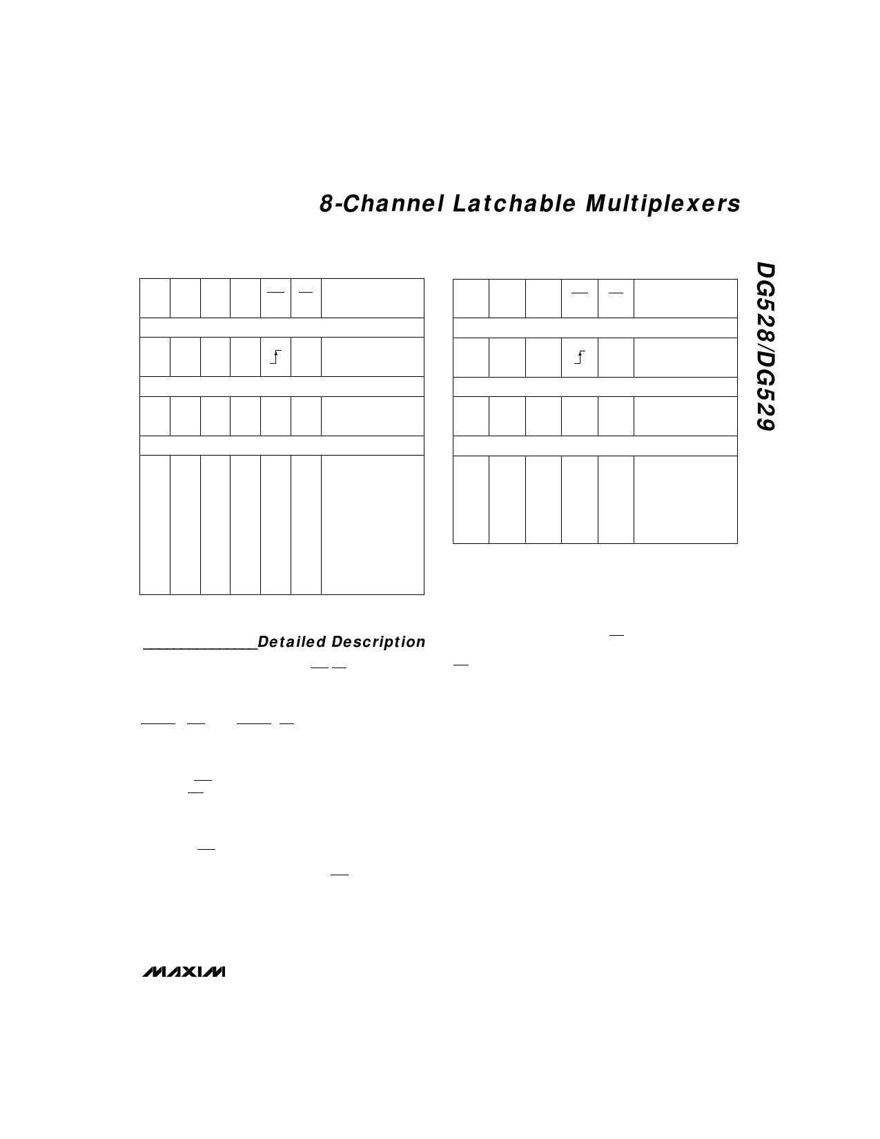
Table 1. DG528 Logic States
A2 A1 A0 EN WR RS
ON SWITCH
Latching
XXXX
Reset
XXXXX
Transparent Operation
XXX00
00010
00110
01010
01110
10010
10110
11010
11110
1
Maintains previous
switch condition
None
0
(latches cleared)
1
None
1
1
1
2
1
3
1
4
1
5
1
6
1
7
1
8
Table 2. DG529 Logic States
A1 A0 EN WR RS
ON SWITCH
Latching
X
X
X
Reset
X
X
X
X
Transparent Operation
X
X
0
0
0
0
1
0
0
1
1
0
1
0
1
0
1
1
1
0
1
Maintains previous
switch condition
None
0
(latches cleared)
1
None
1
1
1
2
1
3
1
4
Note: Logic “1”: VAH ≥ 2.4V, Logic “0”: VAL ≤ 0.8V.
_______________Detailed Description
The internal structures of the DG528/DG529 include
translators for the A2/A1/A0/EN/WR/RS digital inputs,
latches, and a decode section for channel selection
(Truth Tables). The gate structures consist of parallel
combinations of N and P MOSFETs.
WRITE (WR) and RESET (RS) strobes are provided for
interfacing with µP-bus lines (Figure 9), alleviating the
need for the µP to provide constant address inputs to
the mux to hold a particular channel.
When the WR strobe is in the low state (less than 0.8V)
and the RS strobe is in the high state (greater than
2.4V), the muxes are in the transparent mode—they act
similarly to nonlatching devices, such as the DG508A/
DG509A or the HI508/HI509.
When the WR goes high, the previous BCD address
input is latched and held in that state indefinitely. To
pull the mux out of this state, either WR must be taken
low to the transition state, or RS must be taken low to
turn off all channels.
RS turns off all channels when it is low, which resets
channel selection to the channel 1 mode.
The DG528/DG529 work with both single and dual sup-
plies and function over the +5V to +30V single-supply
range. For example, with a single +15V power supply,
analog signals in the 0V to +15V range can be
switched normally. If negative signals around 0V are
expected, a negative supply is needed. However, only
-5V is needed to normally switch signals in the -5V to
+15V range (-5V, +15V supplies). No current is drawn
from the negative supply, so Maxim’s MAX635 DC-DC
converter is an ideal choice.
The EN latch allows all switches to be turned off under
program control. This is useful when two or more
DG528s are cascaded to build 16-line and larger ana-
log-signal multiplexers.
_______________________________________________________________________________________ 7
Share Link: 